


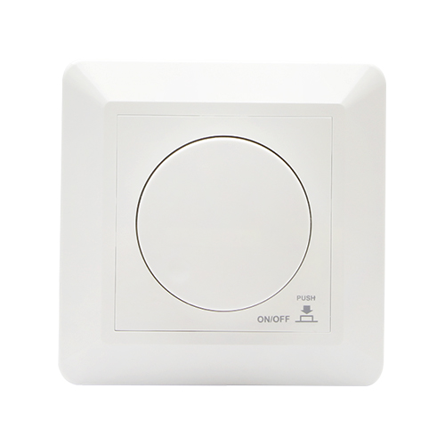
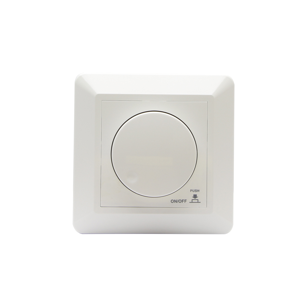
LED調光器 は、家庭やオフィスから商業施設や工業施設まで、さまざまな環境における照明の制御方法に革命をもたらしました。LED調光器は、LED照明の明るさを自在に調整できるため、雰囲気の向上、エネルギー効率の改善、さらには健康増進にも貢献します。この記事では、LED調光器の配線手順を図解入りでご紹介します。
LED調光器の種類
配線作業に入る前に、LED調光器の種類を理解しておきましょう:
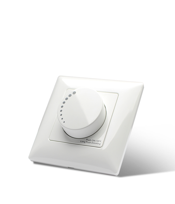
- 位相カット調光器:住宅用途に適した、最も一般的なタイプの調光器です。
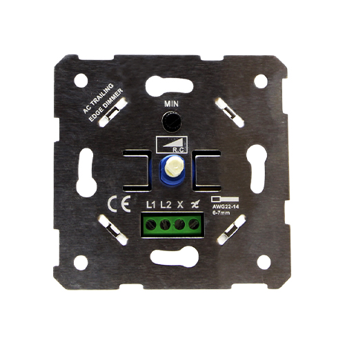
- リーディングエッジおよびトレーリングエッジTRIACディマー:LED調光照明や従来の照明に適した、互換性の高いタイプの調光器です。
- 0-10V調光器:商業用や工業用でよく使用され、精密な制御が可能。
- DALI調光器: これらは通常パネルであり、DALIマスターによって制御され、インテリジェントシステムや人間中心の照明に適している。
- スマート調光器:Wi-FiまたはBluetooth対応の調光器で、スマートフォンや音声コマンドで操作できる。

一般的な調光器の配線作業
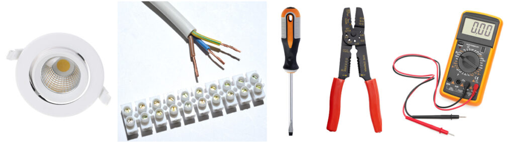
用意されたコンポーネント
- LED照明器具または電球
- LED対応調光スイッチ
- 電線(通常14または12ゲージ)
- ワイヤーナットまたはコネクター
- ドライバー
- ワイヤーストリッパー
- 電圧テスター
- オプションジャンクションボックス
安全上のご注意
- 電気工事を始める前に、必ずブレーカーで電源を切ってください。
- 電圧テスターを使って、電源がオフになっていることを確認する。
- 各地域の電気法規に従ってください。
- 不明な点があれば、資格のある電気技師に相談すること。
ダイアグラム
  +----------------+ +-------------------+
  | | | |
  | LED調光器 |------| LEDドライバ

  +----------------+ +-------------------+
                             |


                     | |
                     | LEDライト
                     | |
                     +----------------+
簡単な共通ステップガイド
ステップ1:電源を切る
サーキットブレーカーで電源を切り、電圧テスターで電源が切れていることを確認する。
ステップ2:ワイヤーの準備
ワイヤーストリッパーを使い、接続する電線の端から絶縁被覆を約半インチ剥ぎ取る。
ステップ3:ワイヤーを特定する
通常、以下のような配線がある:
- 茶/黒:熱線
- 青/白中性線
- 緑/黄色または裸銅:アース線

ステップ4:ディマーの接続
- アース線:調光器からのアース線を電気ボックスのアース線にワイヤーナットを使って接続してください。
- ニュートラルワイヤー:調光器に中性線(通常は白)がある場合は、電気ボックスの中性線に接続してください。
- ホットワイヤー:調光器からの黒線を電気ボックスの黒(ホット)線に接続してください。
ステップ5:LEDライトの接続
- 黒(ホット)ワイヤーのもう一方の端をLEDライトの黒ワイヤーに接続する。
- 白(ニュートラル)ワイヤーのもう一方の端を、LEDライトの白ワイヤーに接続する。
- アース線のもう一方の端をLEDライトのアース線に接続する。
ステップ6:すべての接続を保護する
ワイヤーナットまたは適切なコネクターを使用して、すべての接続を固定してください。裸線が露出しないようにしてください。
ステップ7:テスト
サーキットブレーカーで電源を入れ直し、調光器が期待通りに動作するかテストしてください。
5種類の調光器の詳細ガイド
位相カット調光器
フェーズカット調光器の配線は、高電圧の電気回路を扱う複雑な作業です。配線を誤ると、感電や火災、調光器やその他の電気部品の破損につながる恐れがあります。電気工事の経験がない場合は、資格のある電気技師に相談するか、取り付けを依頼することを強くお勧めします。
とはいえ、もしあなたが電気工事に慣れていて、必要な安全策をすべて講じているのであれば、以下にフェーズカット調光器の配線方法に関する一般的なガイドを示します:
必要な道具と材料
- ドライバー
- ワイヤーストリッパー
- 電気テープ
- ワイヤーナット
- マルチメーター
- フェーズカット調光スイッチ
- 適切な電気ボックスとカバープレート

安全上のご注意
- ブレーカーで作業する回路の電源を切る。
- マルチメーターで電源が切れていることを確認する。
- 手袋や目の保護具など、適切な安全装備を着用すること。
ステップ
- ワイヤーを特定する:電気ボックスを開け、配線を確認します。黒(ホット)線、白(ニュートラル)線、そしておそらく緑か裸銅(アース)線が見えるはずです。
- 調光器の準備:フェーズカット調光器を開梱し、メーカーの説明書をよくお読みください。調光器の配線や端子を確認します。一般的には、黒(または赤)が熱線、白が中性線、緑が接地線です。
- 古いスイッチを外す:古いスイッチを交換する場合は、ワイヤーナットを緩めてワイヤーを切り離す。
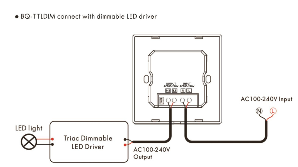
- 照明設備(Dimmable led の運転者)と調光器を接続して下さい: 調光器#4ポートの線とLEDドライバのINPUT-Lポートの線を接続する。LEDドライバーの出力端子(LED+/LED-)を照明器具の入力端子に接続する。(図中のACマークがあるライン)
- ニュートラルワイヤーを接続する:調光器にニュートラル接続が必要な場合は、電気ボックスからの白線を調光器の白線または端子に接続してください。ワイヤーナットを使用して接続を固定してください。
- ホットワイヤーを接続する:電気ボックスからの黒(ホット)線を調光器の黒(または赤)線または端子に接続します。ワイヤーナットを使用して接続を固定してください。
- タック&セキュア:すべてのワイヤーナットがしっかりと固定されていることを確認しながら、慎重にワイヤーを電気ボックスに戻します。
- ディマーの取り付け:メーカーの指示に従い、調光器をボックスにねじ込みます。
- カバープレートの取り付け:カバープレートを調光器の上に取り付けます。
- テスト:サーキットブレーカーで電源を入れ直し、調光器が期待通りに動作しているかテストしてください。


これは一般的なガイドです。必ずメーカーの指示と地域の電気法規に従ってください。不明な点がある場合は、資格のある電気技術者に相談してください。

リーディングエッジおよびトレーリングエッジTRIACディマー
リーディングエッジ調光器とトレーリングエッジ調光器は、照明の明るさを制御するために使用される位相カット調光器の一種です。リーディングエッジ調光器はACサイクルの開始位相をカットし、トレーリングエッジ調光器は終了位相をカットします。このタイプの調光器は、白熱灯、ハロゲン灯、一部のLEDやCFL照明によく使用されます。
注:電気回路の作業は危険です。経験のない方は、資格のある電気技師に相談または依頼することを強くお勧めします。誤った配線は、感電、火災、調光器やその他の電気部品の破損の原因となります。
必要な道具と材料
- ドライバー
- ワイヤーストリッパー
- 電気テープ
- ワイヤーナット
- マルチメーター
- リーディングエッジまたはトレーリングエッジ調光スイッチ
- 電気ボックスとカバープレート
- 安全装備(手袋、保護メガネ)

安全上のご注意
- ブレーカーで作業する回路の電源を切る。
- マルチメーターで電源が切れていることを確認する。
- 手袋や目の保護具など、適切な安全装備を着用すること。
一般的な配線手順
- ワイヤーを特定する:電気ボックスを開け、配線を確認します。通常、黒(ホット)線、白(ニュートラル)線、そしておそらく緑か裸銅(アース)線が見えます。
- 調光器の準備:調光器を開梱し、メーカーの説明書をよくお読みください。調光器の配線や端子を確認します。黒(または赤)がホット、白がニュートラル、緑がアースです。
- 古いスイッチを外す:古いスイッチを交換する場合は、ワイヤーナットを緩めてワイヤーを切り離す。
- 照明設備(Dimmable led の運転者)と調光器を接続して下さい: LEDドライバーのAC入力(N、L)の調光出力(AC100-240V)線を接続します。LEDドライバーの出力端子(LED+/LED-)を照明器具の入力端子に接続する。調光器INPUT(AC100-240V)を電気に接続する。
- ニュートラルワイヤーを接続する:調光器にニュートラル接続が必要な場合は、電気ボックスからの白線を調光器の白線または端子に接続してください。ワイヤーナットを使用して接続を固定してください。
- ホットワイヤーを接続する:電気ボックスからの黒(ホット)線を調光器の黒(または赤)線または端子に接続します。ワイヤーナットを使用して接続を固定してください。
- タック&セキュア:すべてのワイヤーナットがしっかりと固定されていることを確認しながら、慎重にワイヤーを電気ボックスに戻します。
- ディマーの取り付け:メーカーの指示に従い、調光器をボックスにねじ込みます。
- カバープレートの取り付け:カバープレートを調光器の上に取り付けます。
- テスト:サーキットブレーカーで電源を入れ直し、調光器が期待通りに動作しているかテストしてください。

その他の考慮事項
- 互換性:調光器が使用する照明の種類(LED、白熱灯、ハロゲンなど)に対応していることを確認してください。
- 負荷要件:調光器の負荷要件を確認し、制御する照明の総ワット数と一致していることを確認してください。
- マルチ・ウェイ・スイッチング:多方向スイッチング(例:3方向スイッチ)に調光器を設置する場合は、多方向スイッチングに対応した調光器を購入し、多方向スイッチングに特化した配線説明書に従ってください。
必ずメーカーの説明書と地域の電気法規に従ってください。不明な点がある場合は、資格のある電気技術者に相談してください。
0-10V 調光器
0-10V調光制御方式は、特に商業用や工業用の照明制御アプリケーションでは標準的な方式です。この方式では、低電圧信号を用いて照明器具の調光レベルを制御します。電圧信号は、0V(消灯)から10V(全輝度)までの範囲で、その間の明るさは様々です。
基本コンポーネント:
- 0-10V調光機能付き照明器具
- 0-10Vディマーまたはコントローラー
- 低電圧制御ワイヤー(通常18-22 AWG)
- 電源(照明器具に必要なもの)
- オプション自動化システムまたはビル管理システム(BMS)
配線のステップ
- LEDドライバ:照明器具と0-10V調光器がそれぞれの電源に正しく接続されていることを確認してください。
- コントロールワイヤー:0-10V制御信号用に2本の追加ワイヤーが使用されています。1本はプラス制御信号用(+)、もう1本は制御信号グランド用(-)です。
- 照明器具への接続:DIM+"と "DIM-"などと表示されていることがよくあります。
- 調光器への接続:制御線の他端を0-10V調光器またはコントローラの対応する端子に接続します。
- 極性:コントロールワイヤーを接続する際、正しい極性を維持してください。プラス線は器具と調光器の両方の "DIM+"端子に接続し、マイナス線は "DIM-"端子に接続してください。
- オプション・オートメーション:0-10V調光システムをより大きなオートメーションやBMSに組み込む場合は、制御配線がシステムのインターフェースに正しく接続されていることを確認してください。
- テスト:すべての接続が完了したら、システムの電源を入れ、調光機能が期待通りに動作するかテストしてください。

安全上の注意
- 電気配線の作業をする前には、必ず電源を切ってください。
- ワイヤーナットまたは適切なコネクターを使用して、すべての接続を固定します。
- 各地域の電気に関する法令に従ってください。
- 不明な点がある場合は、資格のある電気技術者に相談してください。
0-10V調光システムはその信頼性の高さで知られ、商業ビルや産業環境、そして最近では高度な照明制御システムを備えたスマートホームなど、光量の精密な制御を必要とする用途で広く使用されています。
DALI調光器
DALI(Digital Addressable Lighting Interface)は、建築物の照明を制御するためのプロトコルで、そのシンプルさと堅牢さで知られています。DALI調光器は、DALI対応の照明器具を制御するために使用されます。従来の調光器とは異なり、DALI調光器は照明器具とデジタル通信を行うため、より精密な制御が可能で、グルーピングやシーン設定などの追加機能も備えています。
安全上のご注意
- 作業する回路の電源は、必ずブレーカーで切ってください。
- マルチメーターで電源が切れていることを確認する。
- 手袋や目の保護具など、適切な安全装備を着用すること。
- 電気工事の経験がない場合は、資格のある電気技師に相談するか、雇ってください。
必要な道具と材料
- ドライバー
- ワイヤーストリッパー
- 電気テープまたは熱収縮チューブ
- ワイヤーナットまたは適切なコネクター
- マルチメーター
- DALI調光器
- DALI対応照明器具
- DALIコントロールケーブル(通常2線式、極性フリー)
DALI調光器の一般的な配線手順
- マニュアルを読む:作業を始める前に、DALI調光器とDALI対応照明器具の両方の設置マニュアルを読み、特定の要件と機能を理解してください。
- ネットワークの計画:DALIネットワークは通常デイジーチェーントポロジーで配線されますが、スターやツリートポロジーも可能です。それに応じてネットワークのレイアウトを計画してください。
- 電源を切る:作業する回路の電源をすべて切ってください。
- ディマーへの電源配線:DALI調光器への電源線の接続は、メーカーの指示に従って行ってください。通常、ライブ(ホット)、ニュートラル、場合によってはアースを接続します。
- DALIラインの接続:DALIは、通信に別の2線式制御線を使用します。調光器からDALI対応照明器具にDALI制御線を接続します。DALIは極性フリーなので、配線を逆に接続する心配はありません。
- デイジーチェーンまたはスター構成:レイアウトプランによりますが、DALIコントロールワイヤーをデイジーチェーンまたはスターコンフィギュレーションで各フィクスチャーに接続してください。デイジーチェーンを使用する場合、DALIラインは調光器から1つ目のフィクスチャーへ、そして1つ目のフィクスチャーから2つ目のフィクスチャーへ、というように接続します。
- 住所:DALIシステムによっては、照明器具ごとにアドレスを設定する必要があります。これは通常、別のDALIコントローラーまたはメーカーが提供するソフトウェアを使用して行うことができます。
- 接続のテスト:電源を回復する前に、すべての接続が安全であることを再確認してください。
- 電源の回復とテスト:電源を入れ直し、システムをテストして、調光器が期待通りに照明器具を制御できることを確認してください。
- シーンまたはグループの設定:お使いのDALIシステムがシーンセッティングやフィクスチャーのグループ化のような高度な機能をサポートしている場合は、メーカーの指示に従ってこれらの設定を行うことができます。

DALIシステムは、その機能や要件が大きく異なる場合があるため、最も正確で詳細な情報については、常にメーカーのマニュアルを参照してください。
結論
LED調光器の配線は、手順を注意深く守り、必要な安全対策を講じれば、簡単に行うことができます。LED調光器は、ご家庭の雰囲気を高めたい場合にも、商業施設のエネルギー効率を高めたい場合にも、照明システムに加える価値のあるアイテムです。
