Lighting systems often look simple on the surface. Yet many engineers and buyers struggle to understand how dimming actually works inside LED systems.
A 0–10V dimmer works by sending a 0–10V DC control signal to a compatible LED driver. The driver reads the voltage level and adjusts LED brightness proportionally. Lower voltage produces dimmer light, while 10V provides full brightness.
When I first began working with LED drivers, I noticed that many customers understood LED power supplies but felt confused about dimming control. Among many dimming technologies, 0–10V dimming remained one of the most widely used methods. Its simplicity and reliability still make it a favorite in commercial lighting projects.
What Is a 0–10V Dimmer?
Many lighting buyers hear the term 0–10V dimming frequently. But they often ask a basic question: what exactly does it mean?
A 0–10V dimmer is an analog lighting controller that adjusts brightness by sending a DC voltage signal between 0 and 10 volts to a dimmable LED driver. The voltage level directly controls the light output level.

Definition of 0–10V Dimming Technology
0–10V dimming is one of the earliest electronic lighting control technologies. It works by sending a low-voltage DC signal to the driver.
In simple terms, the dimmer acts like a voltage regulator. It generates a control signal between 0 volts and 10 volts. The LED driver constantly reads this signal. Then it adjusts the LED current output based on the voltage level.
The concept is simple:
| Control Voltage | Light Output |
|---|---|
| 10V | 100% brightness |
| 8V | ~80% brightness |
| 5V | ~50% brightness |
| 2V | ~20% brightness |
| 0–1V | Minimum brightness or OFF |
This system separates power wiring と control wiring. The AC mains power feeds the LED driver. The dimming wires only carry the control signal.
This design makes the system stable and easy to manage.
History and Development of 0–10V Lighting Control
0–10V control did not start with LEDs. It began in fluorescent lighting systems decades ago.
In the early days, fluorescent ballasts used analog voltage control to adjust lamp output. Engineers found this system simple and reliable. It also worked well in large commercial buildings.
Later, when LED lighting became popular, manufacturers adapted the same concept for LED drivers.
The advantage was clear. Building designers already understood the system. Installers already knew the wiring method. So the technology moved smoothly from fluorescent to LED systems.
Even today, many large projects still rely on this mature control method.
Why 0–10V Dimming Is Still Popular in Commercial Lighting
I often see buyers ask why this old technology still exists when digital systems are available.
The answer is simple: reliability and simplicity.
0–10V dimming has several practical advantages.
| 特徴 | Benefit |
|---|---|
| Simple control signal | Easy for installers |
| Low cost components | Lower system price |
| Stable analog signal | Reliable dimming performance |
| Wide compatibility | Works with many drivers |
Many commercial projects care more about reliability and cost than advanced features. Office buildings, warehouses, and retail stores often choose solutions that are easy to maintain.
That is why 0–10V dimming continues to be widely used in modern LED lighting systems.
How Does a 0–10V Dimmer Work?
Many people understand the concept of voltage control. But they still want to know how the system actually changes LED brightness.
A 0–10V dimmer controls brightness by adjusting the control voltage sent to the LED driver. The driver converts that voltage into a proportional LED current output, which directly changes the light intensity.
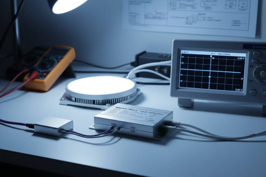
Basic Working Principle of 0–10V Signal Control
The dimming process begins with the dimmer controller.
When a user moves the dimmer slider or knob, the dimmer changes the output voltage. The control voltage ranges between 0V and 10V.
Two low-voltage wires connect the dimmer to the LED driver. These wires carry the signal.
Inside the LED driver, a small control circuit reads the incoming voltage. The driver then translates this voltage into an internal reference signal.
The driver adjusts the LED output current accordingly.
The entire process works in real time. When voltage changes, brightness changes immediately.
Relationship Between Voltage Level and Light Output
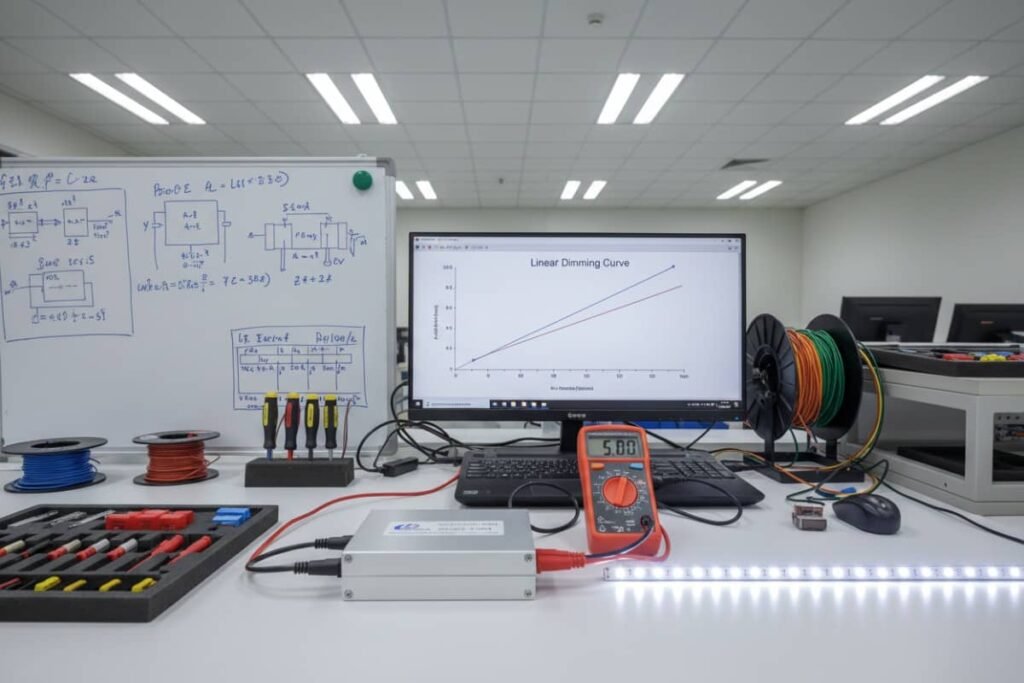
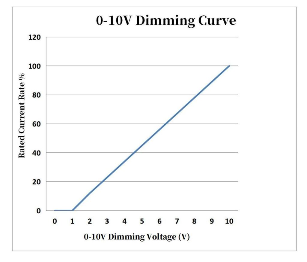
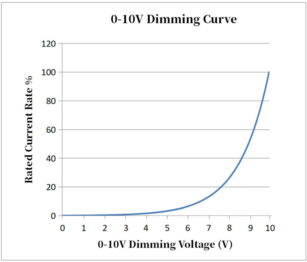
The relationship between voltage and brightness is roughly linear.
This means the output light follows the control voltage proportionally.
| Voltage Level | Driver Response | LED Brightness |
|---|---|---|
| 10V | Maximum output current | 100% |
| 7V | Reduced current | ~70% |
| 5V | Half output current | ~50% |
| 2V | Very low current | ~20% |
| 0–1V | Minimum current | Minimum light |
However, each driver manufacturer may implement slightly different dimming curves.
Some drivers use linear dimming. Others use logarithmic dimming to match human eye perception.
This design improves the visual dimming experience.
How the LED Driver Responds to 0–10V Signals
The LED driver plays the most important role in the system.
The dimmer only sends the signal. The driver performs the actual power control.
Inside the driver, a control circuit converts the analog voltage signal into a current regulation command.
The driver adjusts the output current using internal power electronics.
This process includes several stages.
| Stage | Function |
|---|---|
| Signal detection | Reads control voltage |
| Control processing | Converts voltage to dimming command |
| Current regulation | Adjusts LED output current |
| Output stabilization | Maintains stable light output |
High-quality drivers also include filtering and noise suppression. These features prevent flicker and ensure smooth dimming.
In my experience, the driver quality often determines whether the dimming system performs well.
Key Components of a 0–10V LED Dimming System?
Many buyers assume dimming only involves a dimmer. In reality, the system contains several key components.
A complete 0–10V dimming system includes a dimmer controller, a 0–10V dimmable LED driver, LED fixtures, and low-voltage control wiring that connects the system together.

0–10V Dimmer (Controller)
The dimmer generates the control voltage.
It may appear as a wall switch, a control panel, or a building automation interface.
Its main job is to output a voltage between 0V and 10V.
Some dimmers are manual controllers. Others connect to lighting control systems or building management systems.
Typical features include:
| 特徴 | Function |
|---|---|
| Voltage output | Generates 0–10V signal |
| User interface | Slider, knob, or digital control |
| Multiple channels | Controls several lighting zones |
| Integration ports | Connects to automation systems |
0–10V Dimmable LED Driver
The LED driver converts AC power into regulated DC current for LEDs.
A 0–10V dimmable driver includes an additional control input for dimming signals.
This driver continuously monitors the dimming voltage.
When voltage changes, the driver adjusts the LED current output.
Important driver specifications include:
| パラメータ | Importance |
|---|---|
| 調光範囲 | Determines minimum brightness |
| Current stability | Prevents flicker |
| Response speed | Ensures smooth dimming |
| 互換性 | Works with different dimmers |
LED Lighting Fixtures
The LED fixture contains the LED modules that produce light.
The fixture connects to the driver output.
When the driver changes current, the LEDs change brightness accordingly.
Modern commercial fixtures are designed specifically for dimmable drivers. This ensures stable dimming performance.
Low-Voltage Control Wiring
The control wiring carries the dimming signal.
These wires are separate from the AC power wiring.
Usually, two wires are used:
| Wire | Function |
|---|---|
| Positive (DIM+) | Control signal |
| Negative (DIM−) | Signal return |
Because the voltage is very low, the wiring does not require heavy insulation.
However, installers must still follow good wiring practices to avoid signal interference.
0–10V Dimming Wiring Diagram and Installation?
Even experienced installers sometimes make mistakes when wiring dimming systems.
A standard 0–10V dimming installation connects the dimmer to the LED driver through two low-voltage control wires, while the driver receives AC power separately to operate the LED fixture.
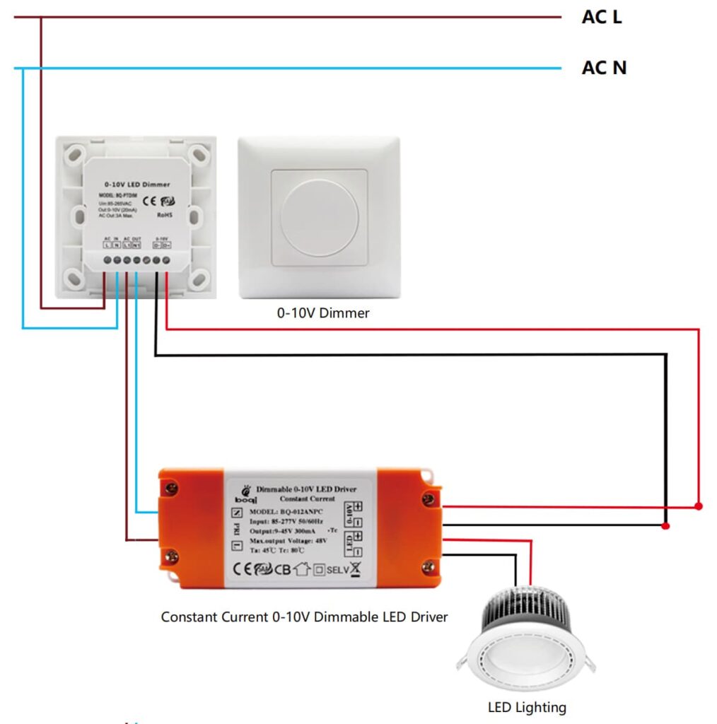
Standard 0–10V Dimming Wiring Configuration
The wiring layout is straightforward.
There are two main circuits.
- AC power circuit
- Low-voltage dimming circuit
The power circuit feeds the LED driver.
The dimming circuit carries the control signal.
| Connection | 説明 |
|---|---|
| AC Line | Provides input power |
| AC Neutral | Completes power circuit |
| DIM+ | Positive dimming signal |
| DIM− | Negative dimming signal |
Multiple LED drivers can share the same dimming signal.
This allows one dimmer to control many fixtures.
Polarity Requirements for Control Wires
Many people think polarity does not matter. In reality, correct polarity is important.
The dimming wires have two terminals:
DIM+ and DIM−.
If the polarity is reversed, the driver may not detect the signal correctly.
Possible problems include:
- No dimming response
- Limited dimming range
- Unstable brightness
Therefore installers should always follow the driver wiring label.
Best Practices for Installation and Safety
Good installation improves system reliability.
Over the years I have seen several simple practices prevent many problems.
| Practice | Reason |
|---|---|
| Separate control wires from power wires | Reduce interference |
| Use shielded cables in long runs | Improve signal stability |
| Keep wiring polarity correct | Ensure proper control |
| Follow driver specifications | Avoid compatibility issues |
These steps may look basic. But they make a big difference in large lighting projects.
Advantages of Using 0–10V Dimming in LED Lighting?
Many lighting technologies exist today. Yet many engineers still choose 0–10V systems.
0–10V dimming provides smooth brightness control, low cost implementation, high reliability, and simple integration with commercial lighting systems.

Smooth and Flicker-Free Dimming
High quality 0–10V systems produce very smooth dimming.
The analog signal changes gradually. This allows the LED driver to adjust current smoothly.
This method reduces flicker problems.
Human eyes are sensitive to sudden brightness changes. Smooth dimming improves visual comfort.
Cost-Effective Lighting Control Solution
Cost matters in large lighting projects.
Compared with digital systems, 0–10V dimming is inexpensive.
The components are simple. The wiring is also straightforward.
| Cost Factor | 0–10V System |
|---|---|
| Dimmer hardware | Low |
| Driver complexity | 中程度 |
| Wiring requirements | Simple |
| Installation cost | Low |
This makes it attractive for projects with hundreds or thousands of fixtures.
Easy Integration with Commercial Lighting Systems
0–10V dimming integrates well with many building control systems.
Lighting control panels, daylight sensors, and occupancy sensors can all output 0–10V signals.
This flexibility makes the system very adaptable.
High Reliability for Large-Scale Projects
Analog systems often prove very reliable.
There are fewer digital communication issues. The system does not depend on complex protocols.
Large buildings often prefer systems that require minimal maintenance.
0–10V Dimming vs Other LED Dimming Technologies?
Different dimming methods exist for LED lighting. Each method has advantages and limitations.
0–10V dimming differs from TRIAC and DALI dimming mainly in signal type, complexity, and system capabilities. Choosing the right method depends on the project requirements.
0–10V vs TRIAC Dimming
TRIAC dimming comes from traditional incandescent lighting.
It works by cutting part of the AC waveform.
| 特徴 | 0–10V | トライアック |
|---|---|---|
| Signal type | Analog DC control | AC phase cutting |
| Wiring | Separate control wires | Same power line |
| 互換性 | Commercial drivers | Residential lighting |
| Flicker risk | Low | Higher |
TRIAC dimming is common in residential lighting.
0–10V works better for commercial systems.
0–10V vs DALI Dimming
DALI is a digital communication protocol.
It allows addressable lighting control.
| 特徴 | 0–10V | ダリ |
|---|---|---|
| Signal type | Analog | デジタル |
| Individual control | No | Yes |
| System complexity | Low | Higher |
| コスト | Lower | Higher |
DALI provides advanced features like scene control and device feedback.
However, it also increases system complexity.
When to Choose Each Dimming Method
Project requirements determine the best dimming method.
| 応用 | Recommended Method |
|---|---|
| Office lighting | 0–10V |
| Residential lighting | トライアック |
| Smart buildings | ダリ |
| Industrial lighting | 0–10V |
In my projects, I often recommend 0–10V for large commercial spaces.
It balances cost, reliability, and performance.
Common Applications of 0–10V Dimming Systems?
0–10V dimming appears in many commercial environments.
The technology is widely used in offices, warehouses, retail spaces, and smart building lighting systems because it provides reliable brightness control for large numbers of fixtures.

Office and Commercial Buildings
Office buildings often require flexible lighting control.
Meeting rooms, workspaces, and corridors all need different brightness levels.
0–10V systems allow centralized control of large lighting zones.
Warehouses and Industrial Lighting
Industrial spaces require durable and simple systems.
Maintenance teams prefer reliable technologies.
0–10V dimming works well with high-bay LED fixtures.
Retail and Architectural Lighting
Retail stores often adjust lighting levels to highlight products.
Architectural lighting also benefits from smooth dimming control.
Smart Building Lighting Control
Many smart building systems still use 0–10V outputs.
Sensors and automation controllers send voltage signals to drivers.
This allows energy-efficient lighting management.
Common Problems and Troubleshooting in 0–10V Dimming?
Even simple systems can experience problems.
Common 0–10V dimming issues include LED flickering, limited dimming range, and signal interference in control wiring. Most problems relate to driver compatibility or installation quality.

LED Flickering During Dimming
Flickering often appears at low brightness levels.
Possible causes include:
- poor driver quality
- unstable dimmer output
- electrical noise
調光範囲の制限
Some systems cannot dim below 20%.
This often depends on driver design.
High quality drivers support deeper dimming.
Signal Interference in Control Wiring
Long control wires can pick up electrical noise.
Installers should separate control wiring from power wiring.
Shielded cables may help in large buildings.
How to Choose the Right 0–10V Dimmer and LED Driver?
Choosing compatible components is critical for system performance.
The right 0–10V dimmer and LED driver should match in signal compatibility, power rating, and certification standards to ensure stable and safe dimming performance.

Checking Compatibility Between Dimmer and Driver
Not every dimmer works with every driver.
Manufacturers may implement slightly different control circuits.
Always check compatibility documentation.
Selecting the Correct Power Rating
The driver must support the LED load.
| パラメータ | Importance |
|---|---|
| Output current | Matches LED module |
| Output power | Supports fixture load |
| Input voltage | Matches supply voltage |
Certifications and Quality Standards to Consider
Commercial projects often require certified components.
Common certifications include:
| 認証 | Region |
|---|---|
| UL | North America |
| CE | Europe |
| FCC | EMI compliance |
Certified products ensure safety and reliability.
FAQ About 0–10V LED Dimming?
Buyers often ask similar questions when selecting dimming systems.
Understanding driver compatibility, system limits, and control capabilities helps buyers design reliable 0–10V dimming systems for commercial lighting projects.
Can a 0–10V Dimmer Work Without a Special LED Driver?
No.
A standard LED driver cannot interpret a 0–10V signal.
You must use a 0–10V dimmable driver designed for this control method.
How Many LED Drivers Can One 0–10V Dimmer Control?
Many drivers can share one dimmer signal.
The limit depends on the dimmer current capacity.
Large systems may control dozens of drivers from one dimmer, like boqi 0-10V dimmer can support 15 units 0-10V dimmable LED Drivers.
What Is the Minimum Dimming Level of 0–10V Systems?
Most drivers dim down to 10% brightness.
Some advanced drivers support 1% or even lower.
Is 0–10V Dimming Suitable for Smart Lighting Systems?
Yes.
Many building control systems still output 0–10V signals.
This allows integration with sensors and automation systems.
結論
0–10V dimming remains one of the simplest and most reliable LED lighting control methods for commercial projects, offering stable performance, smooth dimming, and easy system integration.