Many LED lights flicker, buzz, or fail to dim smoothly with traditional dimmers. This frustrates designers and installers. I often see projects fail simply because the dimming technology does not match the LED driver.
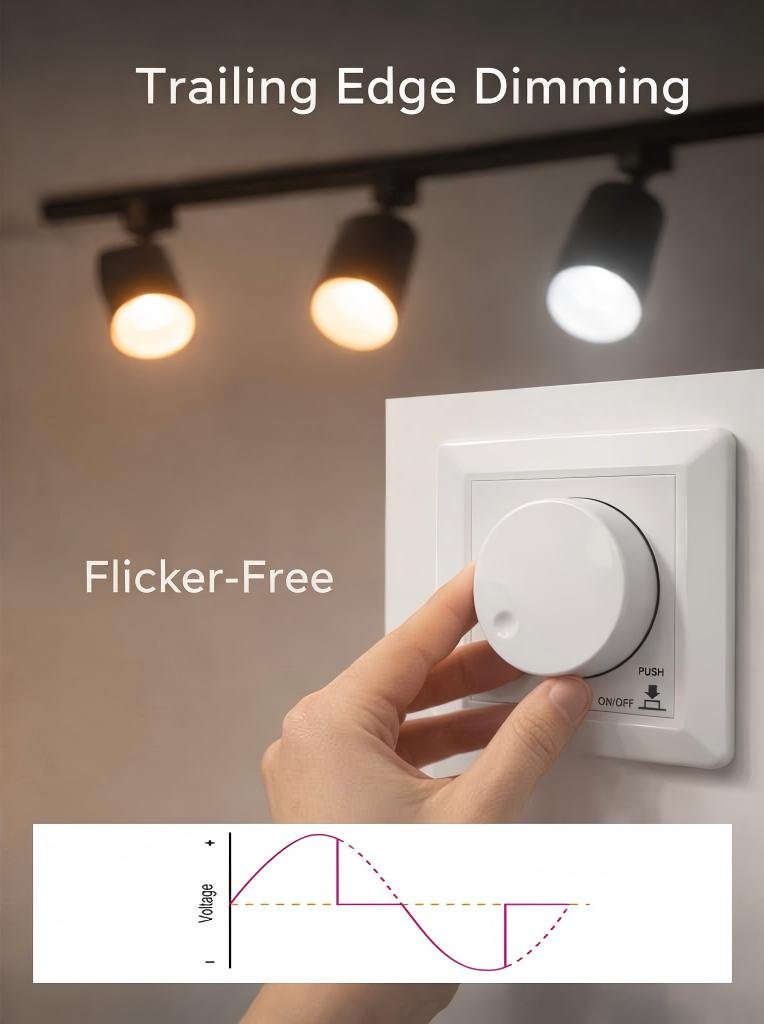
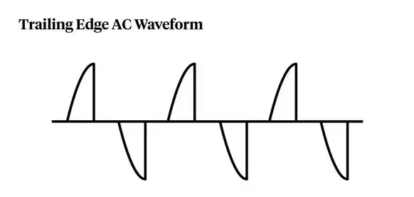
A BQ-TTDIM trailing-edge dimmer controls LED brightness by electronically switching off the AC waveform near the end of each half cycle. This reduces delivered power while maintaining smooth dimming, low noise, and strong compatibility with modern LED drivers.
When I work with LED lighting systems, I always pay close attention to dimming technology. Many problems in lighting projects come from misunderstanding how phase-cut dimming actually works. In this guide, I will explain how the BQ-TTDIM trailing-edge dimmer operates and why it performs so well with LED drivers.
What Is a Trailing Edge Dimmer?
Many installers assume all phase-cut dimmers work the same way. This assumption often causes flicker or unstable light output when LEDs are involved.
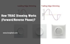
A trailing edge dimmer reduces light intensity by switching off the AC waveform near the end of each half cycle. Instead of cutting the front of the waveform, it trims the back portion to control power delivered to the lamp.
Understanding the Concept
Trailing edge dimming belongs to the phase-cut dimming family. The dimmer modifies the AC sine wave that powers the lighting load. By removing part of the waveform, the dimmer effectively lowers the RMS voltage delivered to the light.
I often explain it in a simple way. Imagine the AC waveform as a continuous wave. The dimmer allows the wave to start normally. Then it turns the current off before the wave finishes. This cut reduces the total energy reaching the lamp.
How Trailing Edge Dimming Works
Phase-Cut Timing
| Phase | Action | Result |
|---|---|---|
| Start of cycle | Voltage flows normally | Lamp receives full voltage momentarily |
| End of cycle | Dimmer switches off output | Reduced total energy |
| Repeat every half cycle | Continuous adjustment | Smooth brightness control |
Why the Method Matters
Trailing edge dimmers work well with electronic loads, especially LED drivers. Many LED drivers contain internal capacitors. These components interact better with a clean voltage rise rather than an abrupt start.
This is why trailing edge dimmers typically produce:
- Less audible noise
- Better low-level dimming
- Reduced flicker
- Higher compatibility with LED drivers
Understanding the Basics of Trailing Edge Dimming
Many lighting professionals understand the term phase-cut dimming but struggle to visualize how the waveform changes.
Trailing edge dimming works by letting the AC voltage start normally and then electronically turning off the current before the waveform finishes each half cycle.
The AC Waveform in Lighting Systems
In a normal power system, voltage follows a sinusoidal waveform. Each cycle includes a positive and negative half.
The dimmer manipulates this waveform. Instead of passing the entire sine wave to the load, it removes part of it.
Comparison of Waveforms
| Mode | Waveform Start | Waveform End | Typical Load |
|---|---|---|---|
| No dimming | Normal | Normal | Full brightness |
| Leading edge | Delayed start | Normal end | Incandescent |
| Trailing edge | Normal start | Early cutoff | LED-drivrutiner |
Why LEDs Prefer Trailing Edge Dimming
LED drivers usually contain switch-mode power supplies. These circuits react differently to voltage changes compared to filament lamps.
Leading edge dimmers introduce a sharp voltage spike at the beginning of each cycle. This spike can create problems like:
- driver stress
- flicker
- noise
- unstable dimming
Trailing edge dimmers avoid this issue. The voltage rises smoothly and only turns off later in the cycle.
Power Reduction Mechanism
Energy Control Table
| Dim Level | Waveform Length | Energy Delivered |
|---|---|---|
| 100% | Full sine wave | Maximum power |
| 75% | Slight cut | Reduced power |
| 50% | Half waveform | Medium power |
| 25% | Large cut | Low power |
The dimmer continuously adjusts the cut point. This dynamic adjustment allows users to control brightness smoothly from full output to low light levels.
Why Trailing Edge Dimmers Are Ideal for Modern LED Lighting
Many lighting engineers discover that older dimmers struggle with LED systems. Flicker and noise appear when incompatible technology is used.
Trailing edge dimmers solve these issues because they work well with electronic LED drivers and low-power loads.

Compatibility with Electronic Drivers
Modern LED drivers contain internal components such as:
- bridge rectifiers
- capacitors
- switching converters
These circuits require stable voltage transitions. Trailing edge dimmers produce smoother switching compared to leading edge devices.
Compatibility Table
| Load Type | Leading Edge | Trailing Edge |
|---|---|---|
| Incandescent lamps | Utmärkt | Bra |
| Halogen lamps | Utmärkt | Bra |
| LED-drivrutiner | Limited | Utmärkt |
| Electronic transformers | Måttlig | Utmärkt |
Improved Low-Load Performance
LED lighting systems usually operate at low wattage. Traditional dimmers often require a minimum load to function correctly.
Trailing edge dimmers are better suited for these low-power conditions. They can maintain stable operation even when the load is small.
Reduced Electrical Noise
Another advantage I often notice is the reduction of electromagnetic interference. Trailing edge dimming generates less electrical noise because the waveform starts naturally.
This improvement results in:
- quieter operation
- less interference with other devices
- smoother dimming response
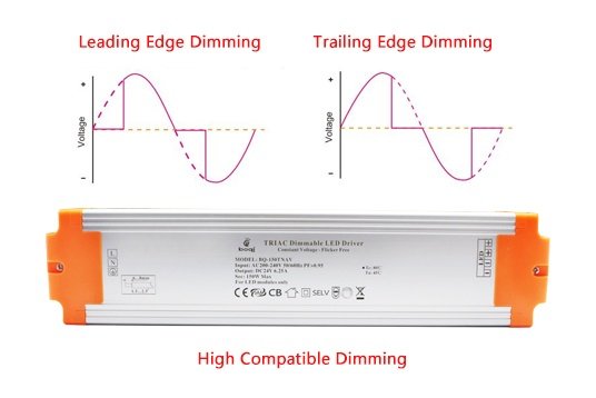
Differences Between Leading Edge and Trailing Edge Dimming
Many people confuse these two dimming technologies. However, their operating principles and performance characteristics are very different.
Leading edge dimmers cut the beginning of the AC waveform, while trailing edge dimmers cut the end portion of the waveform.

Basic Operating Principle
Leading edge dimmers rely on TRIAC components that trigger after a delay. The waveform begins abruptly once the TRIAC fires.
Trailing edge dimmers operate differently. They allow the waveform to start normally and then shut off the current later.
Technical Comparison
| Funktion | Leading Edge | Trailing Edge |
|---|---|---|
| Waveform control | Cuts start | Cuts end |
| Switching component | TRIAC | MOSFET |
| Noise level | Higher | Lower |
| LED compatibility | Måttlig | Utmärkt |
| Dimming smoothness | Limited | Smooth |
Impact on LED Systems
Leading edge dimmers often produce:
- buzzing noise
- visible flicker
- unstable brightness
Trailing edge dimmers minimize these problems because their switching method is gentler.
Practical Example
In many projects I worked on, replacing a leading edge dimmer with a trailing edge unit instantly solved flicker issues. The LED drivers responded much better once the waveform switching changed.
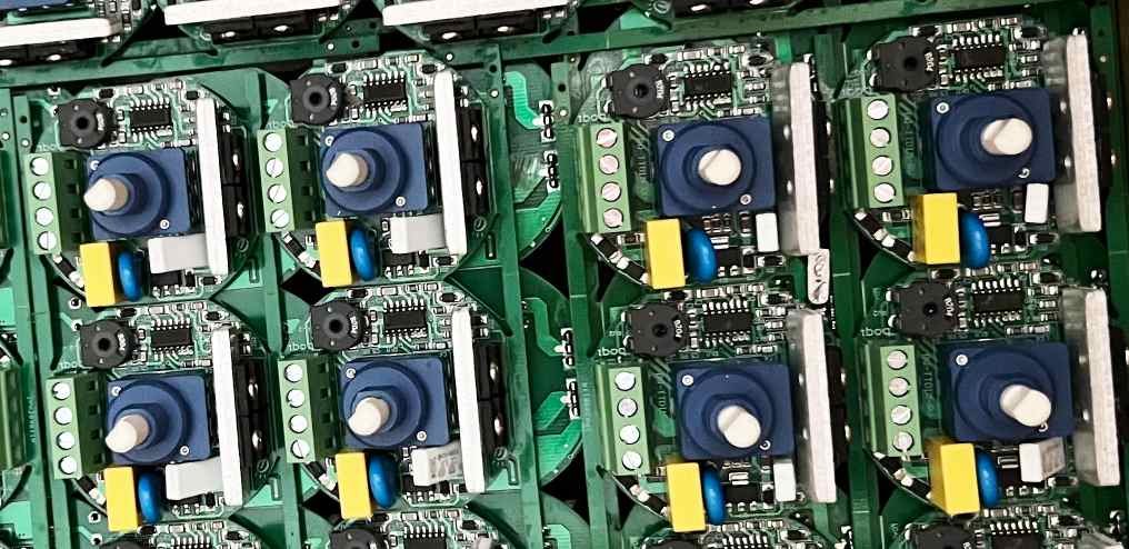
Key Components Inside a Trailing Edge Dimmer
Many users see a dimmer as a simple knob. However, inside the device there is a carefully designed electronic circuit.
A trailing edge dimmer uses semiconductor switches, control circuits, and protection components to regulate the AC waveform.
Main Hardware Elements
Typical components include:
- switching transistors
- control microcircuits
- sensing circuits
- protection modules
These components work together to control the phase cut timing.
Internal Architecture
Component Function Table
| Component | Role |
|---|---|
| MOSFET or transistor | Switches AC current |
| Control IC | Determines dimming angle |
| Kondensatorer | Filter noise |
| Thermal sensor | Prevents overheating |
Interaction of Components
When a user adjusts the knob, the control circuit calculates a new phase angle. The switching transistor then turns off the waveform at the correct moment.
Protection circuits constantly monitor the system. If abnormal conditions occur, the dimmer automatically shuts down to protect itself and the connected load.
This combination of control and protection makes modern trailing edge dimmers reliable for long-term lighting applications.
How Phase-Cut Technology Controls Light Output
Many lighting designers know that dimmers reduce brightness. But fewer understand the electrical mechanism behind this process.
Phase-cut technology controls light output by removing a portion of each AC waveform cycle, which reduces the RMS voltage delivered to the load.
RMS Voltage Reduction
The brightness of many lighting loads depends on the RMS voltage supplied to them.
When the dimmer cuts part of the waveform, the RMS voltage drops. Lower voltage means less electrical power and therefore lower light output.
Power Relationship
Voltage and Power Relationship
| Dim Level | RMS Voltage | Relative Power |
|---|---|---|
| 100% | Full voltage | 100% |
| 75% | Reduced | 75% |
| 50% | Medium | 50% |
| 25% | Low | 25% |
Continuous Control
The dimmer adjusts the cutoff point in every half cycle. This rapid adjustment happens many times per second.
Because AC power cycles quickly, the human eye perceives the light as continuously adjustable rather than flickering.
This technique allows precise brightness control without changing the electrical supply frequency.
The Working Principle of the BQ-TTDIM Trailing Edge Dimmer
Many dimmers appear similar on the outside. However, their internal design and performance can vary significantly.
The BQ-TTDIM trailing edge dimmer controls LED brightness through rotary phase-cut control, allowing users to adjust brightness while maintaining compatibility with dimmable LED drivers and traditional lamps.
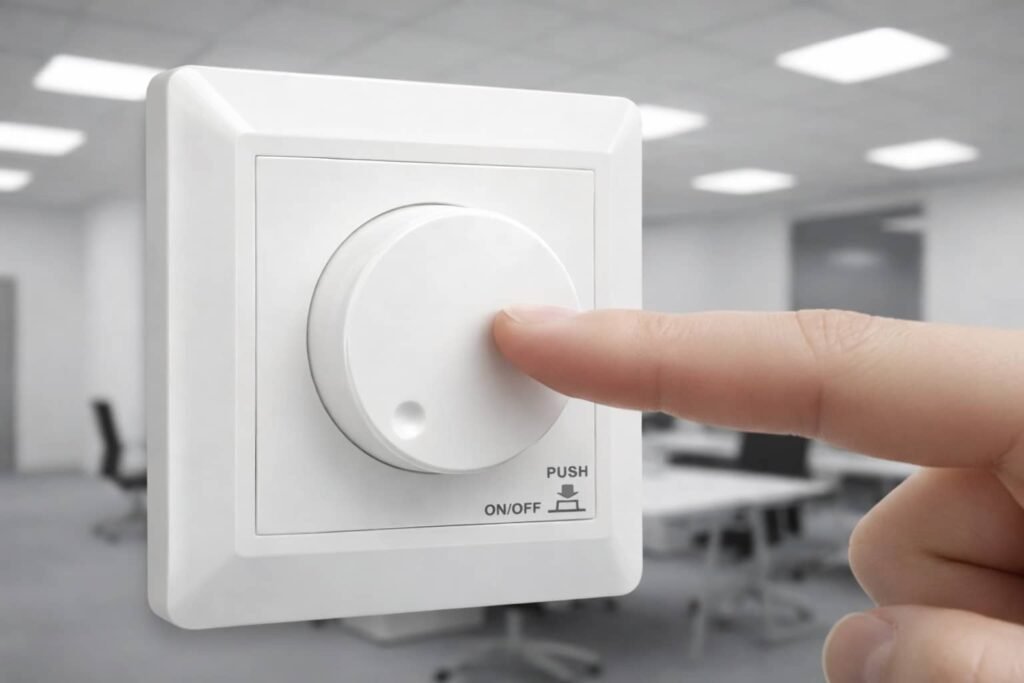
Device Overview
According to the product specification, the BQ-TTDIM is a rotary AC phase-cut dimmer with one output channel designed for dimmable LED lamps, incandescent lights, and halogen lamps.
The device operates within:
| Parameter | Value |
|---|---|
| Input voltage | AC200-240V |
| Output current | Max 1,25A |
| Output power | 3-400W |
| Dimningsområde | 0-100% |
These values come directly from the specification sheet.
Control Interface
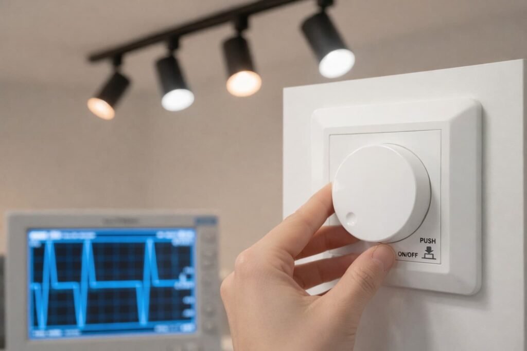
The dimmer uses a rotary knob. Users rotate the knob to change brightness and push it to turn the light on or off.
The device also supports a minimum brightness setting and memory function.
Operating Environment
The dimmer is designed for stable operation in demanding conditions.
| Parameter | Specifikation |
|---|---|
| Operating temperature | −30°C to +55°C |
| Case temperature | Up to 85°C |
| IP rating | IP20 |
These specifications ensure the dimmer can operate reliably in typical indoor installations.
Step-by-Step Process of Trailing Edge Phase Cutting
Many engineers ask how the dimmer actually modifies each AC cycle in real time.
Trailing edge phase cutting works by monitoring the AC waveform and switching off the current near the end of each half cycle.
Phase Control Sequence
Each AC cycle goes through a simple sequence controlled by the dimmer electronics.
Operation Sequence
| Step | Action |
|---|---|
| 1 | Detect zero crossing |
| 2 | Allow voltage to rise normally |
| 3 | Calculate dimming level |
| 4 | Switch off current before waveform end |
| 5 | Repeat every cycle |
Timing Control
The dimmer must control switching with high precision. Even small timing changes can alter brightness.
For example:
- late cutoff → brighter light
- early cutoff → dimmer light
Continuous Feedback
The control circuit repeats this process for every half cycle of AC power. Because AC cycles occur 50 or 60 times per second, the dimming adjustment feels instantaneous to users.
This precise timing control is the core technology behind phase-cut dimming systems.
How the BQ-TTDIM Adjusts Voltage to Dim LED Lights
Many people think a dimmer simply reduces voltage. In reality, it controls the waveform shape rather than directly lowering supply voltage.
The BQ-TTDIM adjusts the effective voltage reaching the LED driver by cutting part of the AC waveform through phase control.
Effective Voltage Control
Instead of changing the supply voltage, the dimmer changes the duration of power delivery.
This technique modifies the RMS voltage seen by the LED driver.
Voltage Adjustment Table
| Cut Angle | Effective Voltage | Light Output |
|---|---|---|
| Small cut | High voltage | Bright |
| Medium cut | Medium voltage | Måttlig |
| Large cut | Low voltage | Dim |
Interaction with LED Drivers
LED drivers interpret the phase-cut waveform and adjust internal current accordingly.
A well-designed driver detects the waveform shape and modifies its output to the LEDs.
Smooth Dimming Behavior
Because the dimmer controls timing very precisely, brightness changes appear smooth and gradual.
This characteristic is important in applications like:
- bostadsbelysning
- hospitality lighting
- architectural lighting
Slutsats
The BQ-TTDIM trailing edge dimmer delivers smooth LED dimming by cutting the AC waveform near the end of each cycle, ensuring quiet operation, high compatibility, and stable lighting performance.