














Molte luci LED sfarfallano, ronzano o non si attenuano in modo fluido con i dimmer tradizionali. Questo frustra progettisti e installatori. Vedo spesso progetti fallire semplicemente perché la tecnologia di dimming non corrisponde al driver LED.
Un dimmer a taglio di fase finale BQ-TTDIM controlla la luminosità dei LED spegnendo elettronicamente la forma d'onda CA vicino alla fine di ogni semiciclo. Ciò riduce la potenza erogata mantenendo un dimming fluido, basso rumore e una forte compatibilità con i driver LED moderni.
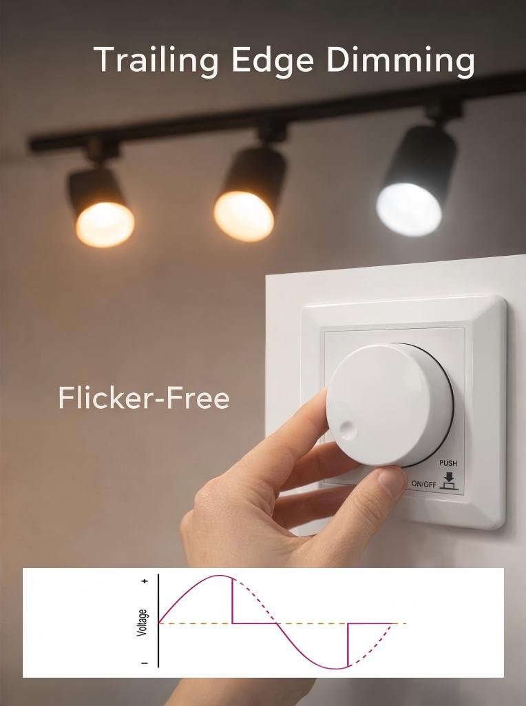
Quando lavoro con sistemi di illuminazione LED, presto sempre molta attenzione alla tecnologia di dimming. Molti problemi nei progetti di illuminazione derivano da una errata comprensione di come funziona effettivamente il taglio di fase. In questa guida, spiegherò come opera il dimmer a taglio di fase finale BQ-TTDIM e perché funziona così bene con i driver LED.
Cos'è un dimmer a trailing edge?
Molti installatori presumono che tutti i dimmer a taglio di fase funzionino allo stesso modo. Questa supposizione causa spesso sfarfallio o emissione luminosa instabile quando sono coinvolti i LED.
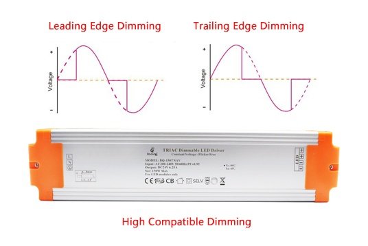
Un dimmer a trailing edge riduce l'intensità luminosa interrompendo la forma d'onda CA verso la fine di ogni semiciclo. Invece di tagliare la parte iniziale della forma d'onda, rifila la porzione finale per controllare la potenza fornita alla lampada.
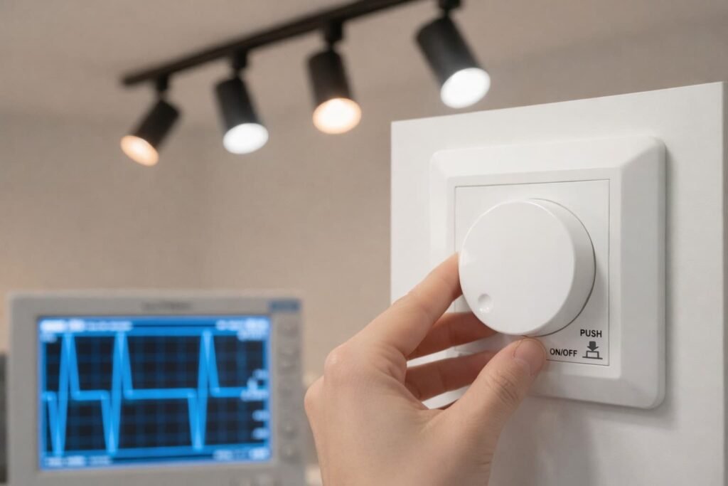
Comprensione del Concetto
La regolazione a trailing edge appartiene alla famiglia del phase-cut dimming. Il dimmer modifica l'onda sinusoidale CA che alimenta il carico di illuminazione. Rimuovendo parte della forma d'onda, il dimmer riduce efficacemente la tensione RMS fornita alla luce.
Spesso lo spiego in modo semplice. Immagina la forma d'onda CA come un'onda continua. Il dimmer consente all'onda di iniziare normalmente. Poi interrompe la corrente prima che l'onda finisca. Questo taglio riduce l'energia totale che raggiunge la lampada.
Come Funziona il Dimming a Taglio di Fase Finale
Temporizzazione del Taglio di Fase
| Fase | Azione | Risultato |
|---|---|---|
| Inizio del ciclo | La tensione scorre normalmente | La lampada riceve piena tensione momentaneamente |
| Fine del ciclo | Il dimmer interrompe l'uscita | Energia totale ridotta |
| Ripetere ogni semiciclo | Regolazione continua | Controllo della luminosità fluido |
Perché il Metodo è Importante
I dimmer a trailing edge funzionano bene con carichi elettronici, soprattutto driver LED. Molti driver LED contengono condensatori interni. Questi componenti interagiscono meglio con un aumento di tensione pulito piuttosto che con un avvio brusco.
Questo è il motivo per cui i dimmer a trailing edge producono tipicamente:
- Meno rumore udibile
- Migliore regolazione a bassi livelli
- Ridotto sfarfallio
- Maggiore compatibilità con i driver LED
Comprensione delle Basi del Dimming a Taglio di Fase Finale
Molti professionisti dell'illuminazione comprendono il termine phase-cut dimming ma faticano a visualizzare come cambia la forma d'onda.
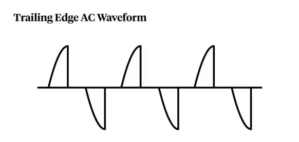
La regolazione a trailing edge funziona lasciando che la tensione CA inizi normalmente e poi interrompendo elettronicamente la corrente prima che la forma d'onda finisca ogni semiciclo.
La Forma d'Onda CA nei Sistemi di Illuminazione
In un sistema di alimentazione normale, la tensione segue una forma d'onda sinusoidale. Ogni ciclo include una semionda positiva e una negativa.
Il dimmer manipola questa forma d'onda. Invece di passare l'intera onda sinusoidale al carico, ne rimuove una parte.
Confronto delle Forme d'Onda
| Modalità | Inizio forma d'onda | Fine forma d'onda | Carico tipico |
|---|---|---|---|
| Nessuna regolazione | Normale | Normale | Piena luminosità |
| Bordo d'attacco | Avvio ritardato | Fine normale | A incandescenza |
| Bordo d'uscita | Avvio normale | Interruzione anticipata | Driver LED |
Perché i LED Preferiscono il Dimming a Taglio di Fase Finale
I driver LED di solito contengono alimentatori a commutazione. Questi circuiti reagiscono diversamente alle variazioni di tensione rispetto alle lampade a filamento.
I dimmer a leading edge introducono un picco di tensione brusco all'inizio di ogni ciclo. Questo picco può creare problemi come:
- stress del driver
- sfarfallio
- rumore
- dimming instabile
I dimmer a taglio posteriore evitano questo problema. La tensione sale gradualmente e si interrompe solo più tardi nel ciclo.
Meccanismo di Riduzione della Potenza
Tabella di Controllo dell'Energia
| Livello di dimming | Lunghezza della forma d'onda | Energia erogata |
|---|---|---|
| 100% | Onda sinusoidale completa | Potenza massima |
| 75% | Taglio lieve | Potenza ridotta |
| 50% | Mezza forma d'onda | Potenza media |
| 25% | Taglio ampio | Bassa potenza |
Il dimmer regola continuamente il punto di taglio. Questa regolazione dinamica consente agli utenti di controllare la luminosità in modo fluido dalla potenza massima ai livelli di luce bassi.
Perché i Dimmer a Taglio di Fase Finale Sono Ideali per l'Illuminazione LED Moderna
Molti ingegneri dell'illuminazione scoprono che i dimmer più vecchi hanno difficoltà con i sistemi LED. Sfarfallio e rumore compaiono quando viene utilizzata una tecnologia incompatibile.
I dimmer a taglio posteriore risolvono questi problemi perché funzionano bene con i driver LED elettronici e i carichi a bassa potenza.

Compatibilità con i Driver Elettronici
I driver LED moderni contengono componenti interni come:
- raddrizzatori a ponte
- condensatori
- convertitori di commutazione
Questi circuiti richiedono transizioni di tensione stabili. I dimmer a taglio posteriore producono una commutazione più fluida rispetto ai dispositivi a taglio anteriore.
Tabella di Compatibilità
| Tipo di Carico | Bordo anteriore | Bordo posteriore |
|---|---|---|
| Lampade a incandescenza | Eccellente | Buono |
| Lampade alogene | Eccellente | Buono |
| Driver LED | Limitata | Eccellente |
| Trasformatori elettronici | Moderato | Eccellente |
Prestazioni Migliorate a Basso Carico
I sistemi di illuminazione LED funzionano solitamente a bassa potenza. I dimmer tradizionali spesso richiedono un carico minimo per funzionare correttamente.
I dimmer a taglio posteriore sono più adatti a queste condizioni di bassa potenza. Riescono a mantenere un funzionamento stabile anche quando il carico è ridotto.
Riduzione del Rumore Elettrico
Un altro vantaggio che noto spesso è la riduzione delle interferenze elettromagnetiche. Il dimming a taglio posteriore genera meno rumore elettrico perché la forma d'onda inizia naturalmente.
Questo miglioramento si traduce in:
- funzionamento più silenzioso
- meno interferenze con altri dispositivi
- risposta di dimming più fluida
Differenze tra Dimming a Taglio di Fase Iniziale e Finale
Molte persone confondono queste due tecnologie di dimming. Tuttavia, i loro principi di funzionamento e le caratteristiche prestazionali sono molto diversi.
I dimmer a taglio anteriore tagliano l'inizio della forma d'onda CA, mentre i dimmer a taglio posteriore tagliano la parte finale della forma d'onda.

Principio di Funzionamento di Base
I dimmer a taglio anteriore si basano su componenti TRIAC che si attivano dopo un ritardo. La forma d'onda inizia bruscamente una volta che il TRIAC si attiva.
I dimmer a taglio posteriore funzionano diversamente. Consentono alla forma d'onda di iniziare normalmente e poi interrompono la corrente più tardi.
Confronto Tecnico
| Caratteristica | Bordo anteriore | Bordo posteriore |
|---|---|---|
| Controllo della forma d'onda | Il taglio inizia | Il taglio termina |
| Componente di commutazione | TRIAC | MOSFET |
| Livello di rumore | Più alta | Inferiore |
| Compatibilità LED | Moderato | Eccellente |
| Fluidità del dimming | Limitata | Fluida |
Impatto sui Sistemi LED
I dimmer a taglio anteriore spesso producono:
- rumore di ronzio
- sfarfallio visibile
- luminosità instabile
I dimmer a taglio posteriore riducono al minimo questi problemi perché il loro metodo di commutazione è più delicato.
Esempio Pratico
In molti progetti su cui ho lavorato, sostituire un dimmer a taglio anteriore con un'unità a taglio posteriore ha risolto immediatamente i problemi di sfarfallio. I driver LED hanno risposto molto meglio una volta cambiata la commutazione della forma d'onda.
Componenti Chiave all'Interno di un Dimmer a Taglio di Fase Finale
Molti utenti vedono un dimmer come una semplice manopola. Tuttavia, all'interno del dispositivo c'è un circuito elettronico progettato con cura.
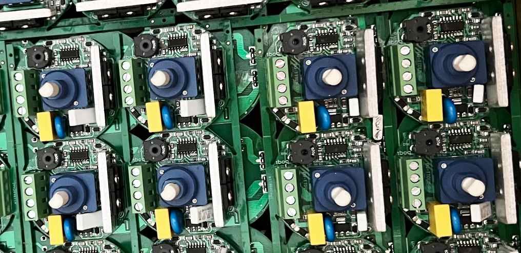
Un dimmer a taglio posteriore utilizza interruttori a semiconduttore, circuiti di controllo e componenti di protezione per regolare la forma d'onda AC.
Elementi Hardware Principali
I componenti tipici includono:
- transistor di commutazione
- microcircuiti di controllo
- circuiti di rilevamento
- moduli di protezione
Questi componenti lavorano insieme per controllare il timing del taglio di fase.
Architettura Interna
Tabella delle Funzioni dei Componenti
| Componente | Ruolo |
|---|---|
| MOSFET o transistor | Commuta la corrente AC |
| IC di controllo | Determina l'angolo di dimming |
| Condensatori | Filtra il rumore |
| Sensore termico | Previene il surriscaldamento |
Interazione dei Componenti
Quando un utente regola la manopola, il circuito di controllo calcola un nuovo angolo di fase. Il transistor di commutazione interrompe quindi la forma d'onda nel momento corretto.
I circuiti di protezione monitorano costantemente il sistema. Se si verificano condizioni anomale, il dimmer si spegne automaticamente per proteggere se stesso e il carico collegato.
Questa combinazione di controllo e protezione rende i moderni dimmer a taglio posteriore affidabili per applicazioni di illuminazione a lungo termine.
Come la Tecnologia a Taglio di Fase Controlla l'Emissione Luminosa
Molti progettisti di illuminazione sanno che i dimmer riducono la luminosità. Ma pochi comprendono il meccanismo elettrico alla base di questo processo.
La tecnologia a taglio di fase controlla l'emissione luminosa rimuovendo una porzione di ogni ciclo della forma d'onda AC, il che riduce la tensione RMS fornita al carico.
Riduzione della Tensione RMS
La luminosità di molti carichi di illuminazione dipende dalla tensione RMS fornita ad essi.
Quando il dimmer taglia parte della forma d'onda, la tensione RMS diminuisce. Una tensione inferiore significa meno potenza elettrica e quindi una minore emissione luminosa.
Relazione di Potenza
Relazione Tensione e Potenza
| Livello di dimming | Tensione RMS | Potenza relativa |
|---|---|---|
| 100% | Tensione piena | 100% |
| 75% | Ridotta | 75% |
| 50% | Medio | 50% |
| 25% | Basso | 25% |
Controllo Continuo
Il dimmer regola il punto di taglio in ogni semi-ciclo. Questa regolazione rapida avviene molte volte al secondo.
Poiché il ciclo di alimentazione AC è rapido, l'occhio umano percepisce la luce come continuamente regolabile anziché tremolante.
Questa tecnica consente un controllo preciso della luminosità senza modificare la frequenza di alimentazione elettrica.
Principio di Funzionamento del Dimmer a Taglio di Fase Finale BQ-TTDIM
Molti dimmer appaiono simili all'esterno. Tuttavia, il loro design interno e le loro prestazioni possono variare in modo significativo.
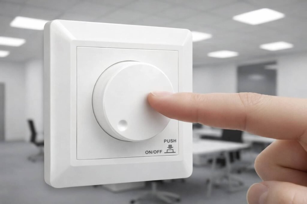
Il dimmer a taglio posteriore BQ-TTDIM controlla la luminosità dei LED tramite controllo rotativo a taglio di fase, consentendo agli utenti di regolare la luminosità mantenendo la compatibilità con driver LED dimmerabili e lampade tradizionali.
Panoramica del Dispositivo
Secondo la specifica del prodotto, il BQ-TTDIM è un dimmer AC rotativo a taglio di fase con un canale di uscita progettato per lampade LED dimmerabili, luci a incandescenza e lampade alogene.
Il dispositivo opera entro:
| Parametro | Valore |
|---|---|
| Tensione di ingresso | AC200-240V |
| Corrente di uscita | Massimo 1,25 A |
| Potenza di uscita | 3-400W |
| Gamma di regolazione | 0-100% |
Questi valori provengono direttamente dalla scheda tecnica.
Interfaccia di Controllo
Il dimmer utilizza una manopola rotativa. Gli utenti ruotano la manopola per cambiare la luminosità e la premono per accendere o spegnere la luce.
Il dispositivo supporta anche una impostazione di luminosità minima e funzione di memoria.
Ambiente Operativo
Il dimmer è progettato per un funzionamento stabile in condizioni impegnative.
| Parametro | Specifica |
|---|---|
| Temperatura di esercizio | da −30°C a +55°C |
| Temperatura della custodia | Fino a 85°C |
| Grado di protezione IP | IP20 |
Queste specifiche garantiscono che il dimmer possa funzionare in modo affidabile nelle tipiche installazioni indoor.
Processo Passo-Passo del Taglio di Fase Finale
Molti ingegneri chiedono come il dimmer modifichi effettivamente ogni ciclo CA in tempo reale.
Il taglio di fase in coda (trailing edge) funziona monitorando la forma d'onda CA e interrompendo la corrente verso la fine di ogni semi-ciclo.
Sequenza di Controllo di Fase
Ogni ciclo CA segue una semplice sequenza controllata dall'elettronica del dimmer.
Sequenza Operativa
| Passo | Azione |
|---|---|
| 1 | Rilevamento del passaggio per lo zero |
| 2 | Consentire alla tensione di salire normalmente |
| 3 | Calcolo del livello di dimming |
| 4 | Interruzione della corrente prima della fine della forma d'onda |
| 5 | Ripetizione per ogni ciclo |
Controllo della Temporizzazione
Il dimmer deve controllare la commutazione con elevata precisione. Anche piccole variazioni di temporizzazione possono alterare la luminosità.
Per esempio:
- taglio tardivo → luce più luminosa
- taglio anticipato → luce più attenuata
Feedback Continuo
Il circuito di controllo ripete questo processo per ogni semi-ciclo dell'alimentazione CA. Poiché i cicli CA si verificano 50 o 60 volte al secondo, la regolazione del dimming risulta istantanea per gli utenti.
Questo controllo preciso della temporizzazione è la tecnologia fondamentale alla base dei sistemi di dimming a taglio di fase.
Come il BQ-TTDIM Regola la Tensione per Attenuare le Luci LED
Molti pensano che un dimmer riduca semplicemente la tensione. In realtà, controlla la forma della forma d'onda anziché abbassare direttamente la tensione di alimentazione.
Il BQ-TTDIM regola la tensione efficace che raggiunge il driver LED tagliando parte della forma d'onda CA attraverso il controllo di fase.
Controllo Efficace della Tensione
Invece di modificare la tensione di alimentazione, il dimmer modifica la durata dell'erogazione di potenza.
Questa tecnica modifica la tensione RMS vista dal driver LED.
Tabella di Regolazione della Tensione
| Angolo di taglio | Tensione efficace | Emissione Luminosa |
|---|---|---|
| Taglio ridotto | Alta tensione | Luminoso |
| Taglio medio | Tensione media | Moderato |
| Taglio ampio | Bassa tensione | Debole |
Interazione con i Driver LED
I driver LED interpretano la forma d'onda a taglio di fase e regolano la corrente interna di conseguenza.
Un driver ben progettato rileva la forma della forma d'onda e modifica la sua uscita verso i LED.
Comportamento di Dimming Fluido
Poiché il dimmer controlla la temporizzazione con grande precisione, le variazioni di luminosità appaiono fluide e graduali.
Questa caratteristica è importante in applicazioni come:
- illuminazione residenziale
- illuminazione alberghiera
- illuminazione architetturale
Conclusione
Il dimmer trailing edge BQ-TTDIM offre un dimming LED fluido tagliando la forma d'onda CA verso la fine di ogni ciclo, garantendo funzionamento silenzioso, elevata compatibilità e prestazioni di illuminazione stabili.