














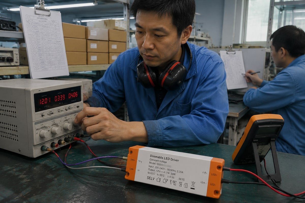
Last quarter, two buyers ordered the wrong drivers because a spec sheet blurred whether 0–10V dimming was analog or digital. On our production line, that confusion costs real money.
0–10V dimming is an analog control method, not digital. It varies a DC control voltage—typically 0 to 10V—to tell a compatible LED driver how much light to produce. Unlike digital protocols such as DALI, it represents dimming level by voltage magnitude, not digital data.
The good news is that the answer becomes obvious once you see how the signal actually works. Below, I will walk through the technology itself, why it counts as analog, how to choose between it and DALI, and how it fits into modern smart systems.
How does 0–10V dimming technology actually work in LED drivers?
Every dimmable driver that leaves our Shenzhen test bench gets swept from 0V to 10V before packing. That daily routine makes the mechanics of this technology very concrete.
0–10V dimming works by feeding a low voltage control signal into an LED driver's dimming input. The driver reads the DC voltage level and maps it to output current. Higher voltage means more light, with 10V typically full output; the datasheet defines the actual minimum level.

The system uses two extra wires that run alongside the mains power lines but stay separate from them. Convention colors these violet for positive and gray or pink for negative. The controller sets a DC voltage on this pair, and the driver measures that voltage to decide its output. In many markets, these control conductors must follow Class 2 wiring requirements, and our own drivers carry SELV markings for the same low-voltage safety reason in IEC regions.
The signal path, step by step
- The wall dimmer or control system establishes a DC voltage between 0 and 10 volts.
- The driver's dimming input reads that voltage level.
- The driver's internal circuit maps the voltage to an output current.
- Interestingly, many drivers then regulate the LEDs internally using Pulse Width Modulation PWM or constant-current reduction—so the interface is analog even when the internals are digital.
What each voltage actually means
| Control voltage | Typical commanded output | Important caveat |
|---|---|---|
| 10V | Full output | The one near-universal point across products |
| 5V | Roughly mid-range | The dimming curve (linear or logarithmic) varies by driver |
| 1V | Near minimum | 1–10V systems per IEC 60929 Annex E bottom out around here |
| 0V | Minimum dim or off | Depends entirely on whether the driver has dim-to-off capability |
Sinking and sourcing current
There are two electrical standards hiding under one name. In current sourcing, the controller supplies the control power. In current sinking, the driver supplies it and the controller pulls the voltage down. Sinking and sourcing current mismatches are one of the most common LED driver compatibility failures we help clients troubleshoot.
0–10V vs. 1–10V: related, not identical
In a 1–10V system, roughly 1V is the minimum dimming command 1, and switching the light fully off is handled separately. A 0–10V system may allow the signal to approach 0V, but whether that produces minimum output or off depends on the driver. Never assume any 0–10V controller behaves correctly with any 1–10V driver.
Why is 0–10V dimming classified as analog instead of digital control?
I learned early in my export career that the word signal misleads people. A client in Germany once insisted our 0–10V drivers must be digital because they used electronics.
0–10V dimming is classified as analog because brightness is set by a continuously variable voltage level, not by discrete coded commands. Digital protocols like DALI send data packets with addresses; 0–10V simply raises or lowers a DC voltage that the driver interprets directly.
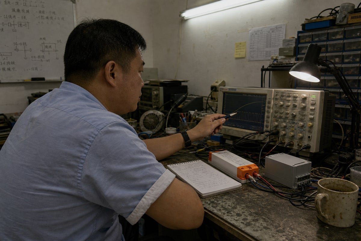
The distinction is simpler than most spec sheets make it sound. An analog signal carries information in the size of a physical quantity. A digital signal carries information in encoded on-off data. With 0–10V, the quantity itself—the voltage magnitude 2—is the message. There is no packet, no address, and no command structure. The driver does not decode anything. It just measures.
Where the confusion comes from
The confusion usually has three sources. First, 0–10V uses wires, controllers, and circuit boards, which can look "smart" even though the method is analog. Second, marketing pages often mix terms loosely when comparing 0–10V with DALI or PWM. Third, many modern drivers convert the incoming analog voltage into an internal Pulse Width Modulation signal to manage the LEDs. That makes the product a hybrid internally, but the control interface—the part that defines the protocol—remains analog. Electronics do not make a system digital. The nature of the signal does.
The analog fingerprint: voltage drop
There is one behavior that proves the point in the field. On long wire runs, analog signals degrade. Voltage drop interference can cause visible dimming inconsistencies across a large installation—installers call it dimming skew. Fixtures at the far end of the run receive a slightly lower voltage and sit at a slightly different level. True digital lighting control systems 3 do not show this fault, because the receiver decodes data rather than measuring a level. When a client in Australia reported uneven brightness across a warehouse ceiling, this analog fingerprint was exactly what we found.
It is also worth remembering that 0–10V is a one-way broadcast. The controller talks; the driver listens. Nothing travels back.
How do I decide between 0–10V and digital protocols like DALI for my product line?
A procurement manager in Singapore recently asked me to quote both options for her private-label range. Her real question was not price. It was which control method fits her market.
Choose 0–10V for simple, low-cost dimming across zones where individual addressing and feedback are unnecessary. Choose DALI when your product line needs fixture-level addressing, two-way status communication, scenes, or building-system integration. Many brands stock both to cover budget and premium project tiers.

Start with a clear DALI protocol comparison, because the two options solve different problems:
| Feature | 0–10V | Digital control such as DALI |
|---|---|---|
| Signal | Analog DC voltage | Digital data |
| How dimming level is represented | Voltage magnitude | Digital command |
| Individual fixture addressing | Generally no | Yes |
| Two-way communication | Generally no | Yes |
| Wiring/system complexity | Relatively simple | More sophisticated |
| Fault/status feedback | Limited | Available in supported systems |
| Typical use | Commercial LED control | Advanced building/lighting control |
For commercial projects, there is a difference that matters more than the analog-versus-digital label itself. 0–10V is generally a one-way control interface. The controller tells the driver what level to produce, but the driver normally does not send information back saying "I'm actually at 37% output," "the LED temperature is too high," or "the driver has failed." That silence is fundamentally different from sophisticated digital lighting control systems. It makes 0–10V simple, robust, and relatively inexpensive—but it also means troubleshooting large installations is harder, because the controller has limited visibility into what is happening at the fixture.
A practical decision checklist
- Does the project need scenes, scheduling, or zoning by individual fixture? If yes, lean DALI.
- Will facilities staff need fault reporting from hundreds of fixtures? If yes, lean DALI.
- Is the budget tight and the control requirement just smooth zone dimming? 0–10V wins.
- Are your installers already trained on simple two-wire control? 0–10V reduces commissioning risk.
Some buyers arrive assuming digital is always better. It is not. In our OEM projects for distributors across Southeast Asia and Europe, 0–10V remains the volume seller precisely because it is broadly supported and hard to break. We usually recommend positioning 0–10V as the reliable core range and DALI as the premium tier, which also protects your margin structure.
Can I integrate 0–10V dimming drivers with digital smart lighting systems?
When we developed our compact SELV driver series, we weighed a real trade-off: keep the analog interface simple, or add hooks for the smart systems our European clients requested.
Yes, you can integrate 0–10V drivers with digital smart lighting systems using bridge modules or hybrid controllers that translate digital commands into an analog voltage. Wireless nodes supporting standards like Matter can convert mesh commands to 0–10V, letting legacy fixtures join modern IoT ecosystems.
The integration pattern is straightforward. A bridge node sits on the digital network—Zigbee, a proprietary mesh, or increasingly Matter—and receives digital commands. It then outputs the corresponding DC voltage on the 0–10V pair. The rise of the Matter smart home standard 4 is actually revitalizing 0–10V, because these translation nodes let legacy industrial fixtures join modern IoT ecosystems without replacing a single driver. For our clients in Japan and the UK who manage retrofit projects, that is often the difference between an affordable upgrade and a full rip-and-replace.
There is one honest limitation you should state in your own product literature. The bridge does not create two-way communication. The smart hub knows what it commanded, not what the fixture actually did. If your project needs real status feedback, the analog interface is still the wrong tool.
Integration checkpoints before you order
| Checkpoint | What to verify | Why it matters |
|---|---|---|
| Sink or source | Match the bridge and driver current method | A mismatch means no dimming at all |
| Minimum dim level | Read the driver datasheet | Control voltage does not guarantee a light percentage |
| Dim-to-off capability | Confirm whether 0V cuts output electronically | Modern dim-to-off drivers eliminate secondary mechanical relays |
| Wire run length | Keep control runs short and gauge adequate | Prevents voltage drop and dimming skew |
| Certifications | Check CE, CB, and SELV marks on the driver | Required for our export markets and yours |
LED driver compatibility is where most integrations fail, so we test every OEM sample against the client's chosen controller before mass production. The industry shift toward dim-to-off drivers is worth watching too: they allow the analog signal itself to cut light output entirely at the 0V threshold, simplifying wiring and cutting installed cost.
Conclusion
0–10V dimming is analog: simple, robust, and still evolving. Read the driver datasheet, match sink and source, and choose digital only when your project truly needs it.
Footnotes
1. The US Department of Energy provides technical resources on advanced lighting controls and dimming performance. ↩︎
2. The IEC sets international standards for electrical voltage measurements and terminology in power systems. ↩︎
3. The DALI Alliance is the global industry organization for the digital lighting control standard. ↩︎
4. The Connectivity Standards Alliance (CSA) is the official body that developed and maintains the Matter standard. ↩︎