














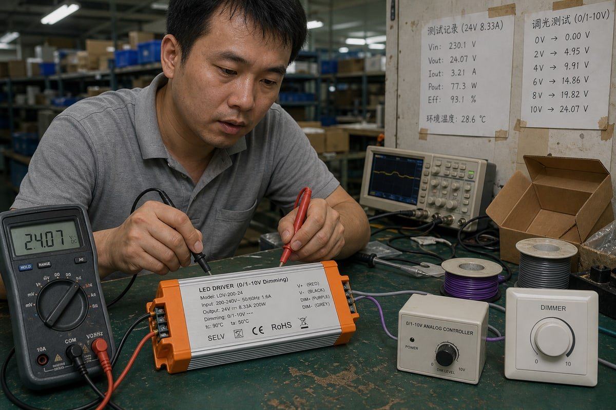
L'année dernière, nos drivers 0–10V diminuaient parfaitement sur notre banc d'essai de Shenzhen, mais le contrôleur d'un client ne pouvait pas les faire varier. La source de courant par rapport à l'absorption de courant dans les systèmes 0–10V en était la cause.
Dans un système de gradation 0–10V, une configuration à source de courant fait générer et fournir le courant de commande par le contrôleur au driver LED, tandis qu'une configuration à puits de courant fait fournir le courant par le driver LED et abaisser la tension par le contrôleur ; les deux appareils doivent avoir des caractéristiques source/puits complémentaires.
La façon la plus simple de s'en souvenir : source de courant signifie contrôleur → fournit le courant → driver. Absorption de courant signifie driver → fournit le courant → contrôleur. Cette seule différence détermine si vos lumières diminuent, se comportent mal ou ignorent complètement le contrôleur. Ci-dessous, je vais vous montrer comment identifier chaque type, choisir le bon, les combiner en toute sécurité et les obtenir auprès d'un fournisseur qui les teste réellement.
Comment puis-je distinguer une source de courant d’un puits de courant dans les systèmes de gradation 0–10V ?
Sur notre banc d'essai de Shenzhen, chaque driver passe un test d'extinction complète avant l'emballage. Cette routine quotidienne a appris à notre équipe à identifier le comportement source et absorption en quelques secondes.
Vérifiez quel appareil alimente la boucle de contrôle. Si le contrôleur émet un signal 0–10V par lui-même, il s'agit d'une source de courant (style ANSI E1.3). Si les fils de gradation du driver LED affichent 10V sans rien de connecté, le driver fournit le courant et attend un contrôleur à absorption (IEC 60929 Annexe E).

La confusion commence parce que le 0–10V ressemble à une interface de signal analogique universelle. Ce n'est pas le cas. La même paire de fils violet et gris peut transporter deux arrangements électriques très différents, et l'étiquette sur la boîte indique rarement lequel vous avez.
Suivez le courant, pas l'étiquette d'application
Vous entendrez souvent un raccourci : la source est théâtrale, l'absorption est commerciale. Je contesterais ce cadre. C'est une règle empirique utile, mais la topologie et la conformité aux normes comptent plus que l'étiquette d'application. ANSI E1.3 1 a formalisé la source de courant dans la gradation théâtrale, où le contrôleur génère la tension. IEC 60929 Annexe E 2 a formalisé l'absorption de courant, issue de l'ère des ballasts fluorescents à absorption et directement intégrée à la gradation moderne des drivers LED. Aujourd'hui, ANSI C137.1 3 définit l'arrangement commercial courant : le driver LED agit comme source de courant via une résistance de tirage interne, et le gradateur mural agit comme absorbeur de courant. Jugez chaque produit par sa topologie et la norme qu'il suit, pas par le marché auquel il a été vendu.
| Question | Système à source de courant | Système à absorption de courant |
|---|---|---|
| Qui génère la tension de contrôle ? | Le contrôleur | Le driver LED |
| Direction du flux de courant | Contrôleur → driver | Driver → contrôleur |
| Norme de référence | ANSI E1.3 | IEC 60929 Annexe E, ANSI C137.1 |
| Racines historiques | Pupitres de gradation théâtraux | Contrôle des ballasts fluorescents à absorption |
| Comportement en circuit ouvert | Dépend du défaut du driver | Augmente généralement à pleine puissance |
Un test rapide au multimètre
Voici ce que nous faisons quotidiennement. Déconnectez le circuit de contrôle à deux fils. Mesurez aux bornes des fils DIM+ et DIM− du driver. Si vous lisez près de 10V DC, le driver fournit le courant et nécessite un contrôleur à absorption. Si les fils de gradation du driver sont proches de 0V tandis que le contrôleur produit la tension par lui-même, vous avez un contrôleur à source. Notez également la polarité du signal pendant la mesure. C'est un signal DC polarisé 4, et savoir quelle borne est positive vous évitera des problèmes plus tard.
Quel type de contrôle 0–10V, source de courant ou puits de courant, convient à mon projet d’éclairage ?
Choisir entre les deux topologies signifie peser le comportement de sécurité contre votre écosystème de contrôle existant. Nous guidons les clients OEM dans ce compromis dans presque chaque projet de développement collaboratif.
Choisissez la sortie en absorption de courant (current sink) pour la plupart des applications de gradation de drivers LED architecturales et commerciales, car la norme ANSI C137.1 fait du driver la source et du gradateur mural le puits (sink), garantissant une pleine sortie en sécurité en cas de circuit ouvert. Choisissez la sortie en source de courant (current source) lorsqu’un contrôleur source, une sortie analogique PLC, ou un système théâtral E1.3 pilote le signal.

Commencez par cette carte rapide, puis lisez le raisonnement ci-dessous.
| Type de projet | Topologie typique | Pourquoi cela convient |
|---|---|---|
| Bureaux, commerce de détail, entrepôts | Gradateur à absorption + driver à source (ANSI C137.1) | Sécurité : un fil de contrôle coupé met les lumières par défaut à 100% |
| Grilles de théâtre et de scène | Contrôleur source (ANSI E1.3) | La console génère le signal ; les luminaires l'interprètent |
| Automatisation industrielle | Contrôleur source via sortie analogique PLC | La plupart des PLC sont par défaut en sorties source |
| Systèmes de gestion de bâtiment | Vérifiez d'abord la conception des entrées/sorties | La capacité de dissipation sur les ports BMS est limitée et doit être vérifiée |
Le point de sécurité par défaut mérite d'être souligné. Dans un système conforme en dissipation, si quelqu'un coupe les câbles de commande, le circuit s'ouvre, la tension interne du driver monte à 10 V, et les lumières passent à pleine puissance. Pour un bureau ou un entrepôt, des lumières bloquées à pleine luminosité sont une nuisance. Des lumières bloquées éteintes sont un incident de sécurité. C'est pourquoi la convention de dissipation s'est imposée dans les bâtiments commerciaux.
Le cas industriel fonctionne dans l'autre sens. Les PLC sont généralement livrés avec des sorties analogiques source. Connectez-en un directement à une configuration prévue pour la dissipation sans vérifier, et vous obtenez un conflit de compatibilité qui peut nécessiter un relais d'interface ou un convertisseur de signal pour être résolu. Nous avons fourni exactement ce type de matériel de pontage à des sociétés d'ingénierie en Allemagne et en Italie.
Contrôle actif vs passif
Une autre couche compte : le contrôle actif vs passif côté dissipation. Une dissipation passive, comme un potentiomètre simple 5, crée des courbes de gradation non linéaires qui changent lorsque vous ajoutez ou retirez des drivers. Une dissipation électronique active maintient un rapport tension/luminosité constant quelle que soit la charge. Nos gradateurs muraux rotatifs utilisent une circuiterie de dissipation active précisément pour cette raison, car un client d'un distributeur remarque quand dix luminaires gradateur différemment de l'échantillon en salle d'exposition.
Puis-je mélanger des dispositifs à source de courant et à absorption de courant dans le même circuit de gradation 0–10V ?
Un responsable des achats à Singapour m'a un jour écrit sur WhatsApp : son échantillon unique gradait magnifiquement, mais le lot pilote de cinquante unités ne descendait pas en dessous de la moitié de la luminosité. La réponse résidait dans les calculs de courant source et dissipation.
Vous ne devez pas mélanger des dispositifs source de courant et dissipation de courant à moins qu'un côté ne soit conçu pour gérer les deux. Associez un driver source avec un contrôleur dissipation, ou un contrôleur source avec un driver dissipation, et vérifiez toujours que la capacité totale de dissipation du contrôleur couvre le courant source de chaque driver en parallèle.

L'hypothèse dangereuse dans ce métier est simple : si deux produits indiquent 0–10 V, ils sont compatibles. Ils ne le sont pas nécessairement. Une étiquette 0–10 V indique l'interface de tension de commande. Elle n'indique pas la topologie, le courant source/dissipation, le comportement de polarité, ni l'implémentation exacte de la norme. Deux dispositifs incompatibles peuvent être sur les mêmes deux fils et simplement se parler sans se comprendre, produisant des plages de gradation erronées ou aucune réponse du tout.
Faites le calcul du courant absorbé
Dans un réseau en dissipation, chaque driver ajouté en parallèle contribue son propre courant source à la boucle. Le contrôleur doit dissiper la somme de tous ces courants pour tirer la ligne à 0 V. Ne vous contentez donc pas de compter les drivers. Calculez :
Courant total de dissipation ≈ nombre de drivers × courant source du driver
Comparez ensuite ce nombre avec la capacité de dissipation spécifiée du contrôleur, mesurée en mA. Voici un exemple chiffré avec des valeurs illustratives :
| Drivers sur la boucle | Courant source total (à 1 mA chacun, exemple) | Contrôleur nominal pour dissiper 5 mA | Contrôleur nominal pour dissiper 30 mA |
|---|---|---|---|
| 1 | 1 mA | Fonctionne | Fonctionne |
| 5 | 5 mA | Limite, courbe déformée | Fonctionne |
| 10 | 10 mA | Impossible d'atteindre le niveau minimum | Fonctionne |
C'est exactement ce qui s'est passé dans ce pilote à Singapour : un driver gradait parfaitement, mais dix drivers dépassaient la capacité de dissipation du contrôleur, donc la ligne ne pouvait jamais être tirée assez bas.
Détails de câblage qui posent problème
Au-delà des calculs, surveillez quatre choses. Premièrement, la polarité du signal : 0–10 V est un signal DC polarisé, et inverser DIM+ et DIM− empêchera la gradation ou peut endommager le contrôleur. Deuxièmement, la chute de tension sur les longues lignes de commande, qui comprime silencieusement votre plage de gradation. Troisièmement, la mise à la terre : une référence flottante dans les drivers en dissipation peut provoquer un scintillement lorsque la terre du signal de commande dérive par rapport à la référence interne du driver. Quatrièmement, les contrôleurs 0–10 V sans fil modernes récupèrent souvent leur puissance de fonctionnement à partir du courant source du driver, donc ils ne fonctionnent qu'avec des drivers réellement source.
Avant de connecter quoi que ce soit, exécutez cette liste de contrôle :
- Identifiez la topologie : source ou dissipation ?
- Vérifiez le courant source : combien de mA chaque driver fournit-il ?
- Vérifiez la capacité de dissipation : combien de mA le contrôleur peut-il absorber ?
- Vérifiez la polarité : confirmez DIM+ et DIM−.
- Vérifiez la norme : ne supposez pas que chaque interface 0–10 V se comporte de manière identique.
- Vérifiez la sortie minimale : confirmez ce que le driver fait réellement à 0 V, pas ce que la fiche technique appelle 0%.
- Testez la combinaison complète : contrôleur, le nombre réel de drivers, et la charge LED réelle.
Comment choisir un fournisseur fiable de drivers LED pour les systèmes 0–10V à source de courant ou à absorption de courant ?
Deux décennies dans cette industrie m'ont appris une leçon difficile : les acheteurs regrettent rarement d'avoir posé des questions techniques exigeantes, mais ils regrettent souvent d'avoir supposé que la fiche technique racontait toute l'histoire.
Choisissez un fournisseur qui publie les valeurs nominales de courant source et puits, précise quelle norme chaque interface 0–10V suit, teste les combinaisons contrôleur-plus-variateur en quantités réelles, et propose un support d'ingénierie OEM/ODM. Un partenaire fiable vérifie toute la plage de gradation avant expédition, pas seulement l'étiquette 0–10V sur la fiche technique.
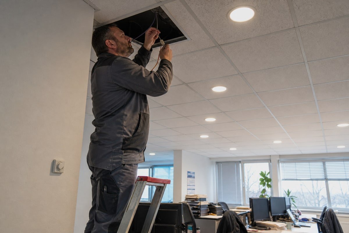
La véritable question de compatibilité n'est jamais " les deux produits sont-ils 0–10 V ? " mais " ce contrôleur peut-il piloter électriquement ce nombre exact de ces drivers sur toute la plage de variation requise ? " Un fournisseur qui ne peut pas répondre à cette question concernant ses propres produits vous laissera y répondre lors de la mise en service, à vos frais et dans vos délais.
Voici le cadre d'évaluation que j'encourage nos clients distributeurs et de marque privée à utiliser, car c'est celui auquel nous nous tenons nous-mêmes :
| Que demander | Feu vert | Feu rouge |
|---|---|---|
| Quelle norme l'interface suit-elle ? | Cite explicitement IEC 60929 Annexe E, ANSI C137.1, ou E1.3 | Dit seulement " 0–10V standard " |
| Quelle est la spécification de source/sink (source/puits) du courant ? | Publie les valeurs en mA pour les deux rôles | Plage de tension uniquement |
| Pouvez-vous tester ma combinaison exacte ? | Teste sur banc le contrôleur + la quantité + la charge | " Cela devrait fonctionner " |
| Que se passe-t-il à 0V ? | Indique le comportement réel de sortie minimale | Répète " 0% " sans contexte |
| Certifications et marquages ? | CE, CB, SAA, SELV visibles sur l'étiquette | Marquages vagues ou absents |
| Support de personnalisation ? | Développement OEM/ODM, impression de logo, étiquetage des bornes | Ventes uniquement sur catalogue |
Sur notre propre ligne, chaque driver est expédié dans un boîtier en aluminium avec ailettes de dissipation thermique et bornes clairement imprimées L, N, LED et 0–10V, car des étiquettes de câblage ambiguës causent une part surprenante d'erreurs de polarité sur le terrain. Avant qu'un lot ne parte pour Singapour, le Japon, l'Allemagne ou l'Australie, nous testons le contrôleur spécifié par le client contre la quantité réelle de drivers et la charge LED, sur toute la plage de gradation. Lorsqu'un client en France avait besoin d'un gradateur à sink (puits) apparié à des drivers d'approvisionnement tiers, nos ingénieurs ont d'abord demandé la spécification de courant source des drivers et ont dimensionné l'étage de sink en conséquence. C'est le niveau de détail qu'il vaut la peine d'exiger de tout partenaire, y compris nous. Cela protège le coût de votre projet, votre délai et le nom de votre marque sur la boîte.
Conclusion
Source de courant vs sink de courant dans les systèmes 0–10V est une question de compatibilité, pas une étiquette. Faites correspondre les topologies, vérifiez la capacité de sink et testez des combinaisons complètes avant que tout driver ne soit expédié.
Notes de bas de page
Le programme de normes techniques ESTA maintient la norme ANSI E1.3 pour le contrôle 0-10V théâtral. ↩︎
La boutique en ligne de la Commission électrotechnique internationale fournit la norme officielle IEC 60929 pour le contrôle de l'éclairage. ↩︎
Site officiel de NEMA, l'organisme responsable de la norme d'interface d'éclairage ANSI C137.1. ↩︎
Explique la nature des signaux de courant continu où la polarité est un facteur critique. ↩︎
Définition technique d'un potentiomètre, utilisé comme sink passif dans les circuits de gradation analogiques. ↩︎