














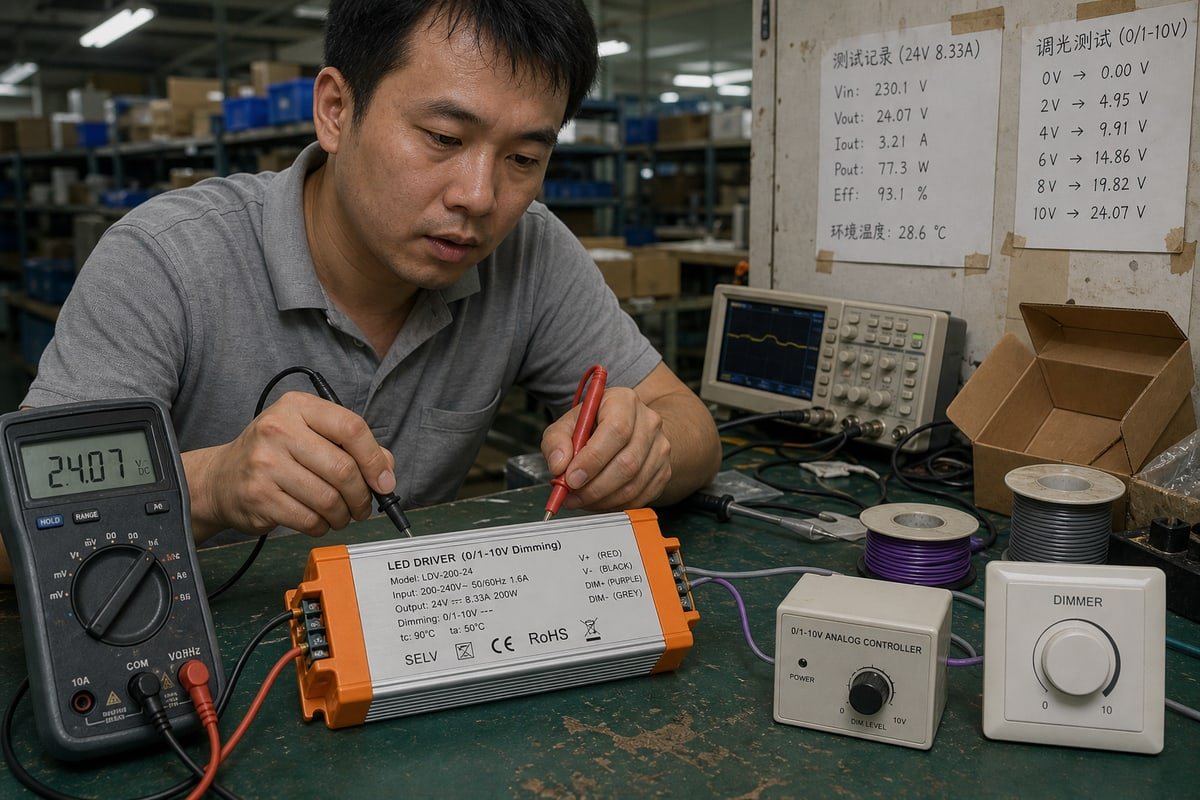
ปีที่แล้ว ไดรเวอร์ 0–10V ของเราดิมได้อย่างสมบูรณ์แบบบนแท่นทดสอบที่เซินเจิ้น แต่คอนโทรลเลอร์ของลูกค้ารายหนึ่งไม่สามารถควบคุมได้ สาเหตุคือ current source กับ current sink ในระบบ 0–10V.
ในระบบการปรับแสง 0–10V การตั้งค่าแบบแหล่งจ่ายกระแส (current-source) จะให้คอนโทรลเลอร์สร้างและจ่ายกระแสควบคุมไปยังไดรเวอร์ LED ในขณะที่การตั้งค่าแบบตัวรับกระแส (current-sink) จะให้ไดรเวอร์ LED จ่ายกระแสและคอนโทรลเลอร์ดึงแรงดันไฟฟ้าลง อุปกรณ์ทั้งสองต้องมีคุณสมบัติแหล่งจ่าย/ตัวรับที่สอดคล้องกัน.
วิธีจำที่ง่ายที่สุด: current source หมายถึงคอนโทรลเลอร์ → จ่ายกระแส → ไดรเวอร์ ส่วน current sink หมายถึงไดรเวอร์ → จ่ายกระแส → คอนโทรลเลอร์ ความแตกต่างเพียงจุดนี้决定ว่าไฟของคุณจะดิมได้正常工作 ทำงานผิดปกติ หรือไม่ตอบสนองต่อคอนโทรลเลอร์เลย ด้านล่างนี้ ผมจะแสดงวิธีระบุแต่ละประเภท เลือกประเภทที่ถูกต้อง ใช้งานร่วมกันอย่างปลอดภัย และเลือกซื้อจากซัพพลายเออร์ที่ทดสอบจริง.
ฉันจะแยกความแตกต่างระหว่างแหล่งจ่ายกระแส (current source) และตัวรับกระแส (current sink) ในระบบปรับแสง 0–10V ได้อย่างไร?
บนแท่นทดสอบที่เซินเจิ้น ไดรเวอร์ทุกตัวผ่านการตรวจสอบการดิมจนมืดก่อนบรรจุ กิจวัตรประจำวันนี้สอนให้ทีมของเราระบุพฤติกรรม source และ sink ได้ในไม่กี่วินาที.
ตรวจสอบว่าอุปกรณ์ใดจ่ายไฟให้วงจรควบคุม หากคอนโทรลเลอร์จ่ายสัญญาณ 0–10V ได้เอง แสดงว่าเป็น current source (แบบ ANSI E1.3) หากสาย DIM ของไดรเวอร์ LED แสดงค่า 10V เมื่อไม่ได้เชื่อมต่ออะไร แสดงว่าไดรเวอร์เป็นฝ่ายจ่ายกระแส และคาดหวังให้คอนโทรลเลอร์เป็นตัวรับ (แบบ IEC 60929 Annex E).
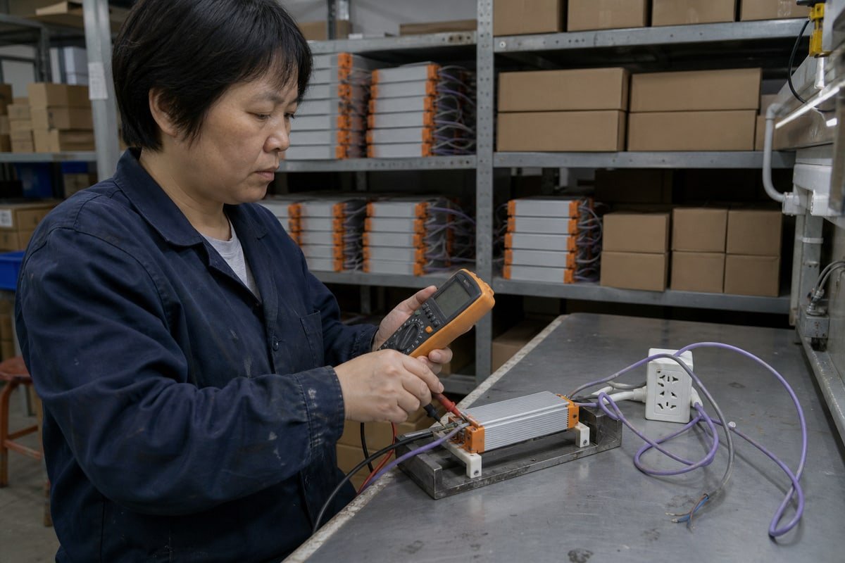
ความสับสนเกิดจาก 0–10V ดูเหมือนอินเทอร์เฟซสัญญาณอนาล็อกสากลเพียงหนึ่งเดียว แต่จริงๆ แล้วไม่ใช่ สายคู่สีม่วงและสีเทาคู่เดียวกันสามารถรองรับการจัดเรียงทางไฟฟ้าที่แตกต่างกันสองแบบ และฉลากบนกล่องแทบไม่เคยบอกว่าคุณมีแบบไหน.
ตามกระแส อย่าตามฉลากการใช้งาน
คุณมักจะได้ยินคำพูดสั้นๆ ว่า sourcing ใช้ในงานโรงละคร sinking ใช้ในงานเชิงพาณิชย์ ผมอยากจะโต้แย้งมุมมองนั้น มันเป็นกฎง่ายๆ ที่มีประโยชน์ แต่โครงสร้างวงจรและการปฏิบัติตามมาตรฐานสำคัญกว่าฉลากการใช้งาน. ANSI E1.3 1 กำหนดมาตรฐาน current sourcing ในระบบดิมสำหรับโรงละคร โดยคอนโทรลเลอร์เป็นผู้สร้างแรงดันไฟฟ้า. IEC 60929 Annex E 2 กำหนดมาตรฐาน current sinking ซึ่งพัฒนามาจากยุคบัลลาสต์แบบ sinking สำหรับหลอดฟลูออเรสเซนต์ และส่งต่อมาสู่การดิมไดรเวอร์ LED สมัยใหม่ ปัจจุบัน, ANSI C137.1 3 กำหนดรูปแบบเชิงพาณิชย์ทั่วไป: ไดรเวอร์ LED ทำหน้าที่เป็น current source ผ่านตัวต้านทาน pull-up ภายใน และสวิตช์ดิมบนผนังทำหน้าที่เป็น current sink ควรตัดสินผลิตภัณฑ์แต่ละตัวจากโครงสร้างวงจรและมาตรฐานที่ปฏิบัติตาม ไม่ใช่จากตลาดที่จำหน่าย.
| คำถาม | ระบบ Current Source | ระบบ Current Sink |
|---|---|---|
| ใครเป็นผู้สร้างแรงดันควบคุม? | คอนโทรลเลอร์ | ไดรเวอร์ LED |
| ทิศทางการไหลของกระแส | คอนโทรลเลอร์ → ไดรเวอร์ | ไดรเวอร์ → คอนโทรลเลอร์ |
| มาตรฐานอ้างอิง | ANSI E1.3 | IEC 60929 Annex E, ANSI C137.1 |
| ต้นกำเนิดทางประวัติศาสตร์ | แผงควบคุมดิมสำหรับโรงละคร | การควบคุมบัลลาสต์แบบ sinking สำหรับหลอดฟลูออเรสเซนต์ |
| พฤติกรรมเมื่อวงจรเปิด | ขึ้นอยู่กับค่าเริ่มต้นของไดรเวอร์ | โดยทั่วไปจะเพิ่มเป็นเอาต์พุตเต็ม |
การทดสอบมัลติมิเตอร์อย่างรวดเร็ว
นี่คือสิ่งที่เราทำทุกวัน ถอดวงจรควบคุมสองสายออก วัดขั้ว DIM+ และ DIM− ของไดรเวอร์ หากอ่านค่าได้ใกล้ 10V DC แสดงว่าไดรเวอร์เป็นฝ่ายจ่ายกระแส (sourcing) และต้องใช้คอนโทรลเลอร์แบบรับกระแส (sinking) หากขั้ว DIM ของไดรเวอร์อยู่ใกล้ 0V ในขณะที่คอนโทรลเลอร์จ่ายแรงดันได้เอง แสดงว่าคุณมีคอนโทรลเลอร์แบบจ่ายกระแส (sourcing) นอกจากนี้ ควรสังเกตขั้วสัญญาณขณะวัดด้วย นี่คือ สัญญาณ DC แบบมีขั้ว 4, และการรู้ว่าขั้วใดเป็นบวกจะช่วยให้คุณไม่เจอปัญหาในภายหลัง.
ระบบควบคุมแบบ 0–10V แบบใด ระหว่าง current source หรือ current sink ที่เหมาะสมกับโครงการไฟส่องสว่างของฉัน?
การเลือกระหว่างสองโครงสร้างนี้หมายถึงการชั่งน้ำหนักระหว่างพฤติกรรม fail-safe กับระบบควบคุมที่คุณมีอยู่แล้ว เราอธิบายข้อแลกเปลี่ยนนี้ให้ลูกค้า OEM ในแทบทุกโครงการพัฒนาร่วมกัน.
เลือก current sink สำหรับการหรี่แสง LED driver ในงานสถาปัตยกรรมและเชิงพาณิชย์ส่วนใหญ่ เนื่องจาก ANSI C137.1 กำหนดให้ driver เป็น source และ wall dimmer เป็น sink ซึ่งให้ผลลัพธ์เต็มกำลังอย่างปลอดภัยเมื่อวงจรเปิด เลือก current source เมื่อใช้ตัวควบคุมแบบ sourcing, เอาต์พุตแอนะล็อกจาก PLC หรือระบบ E1.3 สำหรับโรงละครเป็นตัวขับสัญญาณ.

เริ่มจากแผนผังสรุปนี้ แล้วอ่านเหตุผลด้านล่าง.
| ประเภทโครงการ | โครงสร้างทั่วไป | เหตุผลที่เหมาะสม |
|---|---|---|
| สำนักงาน ร้านค้าปลีก โกดัง | ตัวรับกระแส (sinking dimmer) + ไดรเวอร์แบบจ่ายกระแส (sourcing driver) (ANSI C137.1) | Fail-safe: สายควบคุมขาดจะทำให้ไฟกลับเป็น 100% |
| โรงละครและโครงสร้างเวที | คอนโทรลเลอร์แบบซอร์สซิ่ง (ANSI E1.3) | คอนโซลสร้างสัญญาณ ฟิกซ์เจอร์เป็นตัวตีความ |
| ระบบอัตโนมัติในอุตสาหกรรม | คอนโทรลเลอร์แบบซอร์สซิ่งผ่านเอาต์พุตแอนะล็อกจาก PLC | PLC ส่วนใหญ่ตั้งค่าเริ่มต้นเป็นเอาต์พุตแบบซอร์สซิ่ง |
| ระบบจัดการอาคาร | ตรวจสอบการออกแบบ I/O ก่อนเสมอ | ความสามารถในการซิงก์ของพอร์ต BMS มีจำกัดและต้องตรวจสอบ |
จุดปลอดภัยเมื่อเกิดความล้มเหลวสมควรได้รับการเน้นย้ำ ในระบบซิงก์ที่ถูกต้อง หากมีคนตัดสายควบคุม วงจรจะเปิด ดriver แรงดันภายในจะเพิ่มขึ้นเป็น 10V และไฟจะกระโดดไปที่เอาต์พุตเต็ม สำหรับสำนักงานหรือคลังสินค้า ไฟที่ติดค้างที่ความสว่างเต็มที่เป็นเพียงความรำคาญ แต่ไฟที่ติดค้างในสถานะปิดคืออุบัติเหตุด้านความปลอดภัย นี่คือเหตุผลที่มาตรฐานซิงก์ชนะในอาคารพาณิชย์.
กรณีอุตสาหกรรมเป็นไปในทางตรงกันข้าม PLC มักมาพร้อมเอาต์พุตแอนะล็อกแบบซอร์สซิ่ง หากเชื่อมต่อโดยตรงกับระบบที่คาดหวังแบบซิงก์โดยไม่ตรวจสอบ คุณจะพบกับความขัดแย้งด้านความเข้ากันได้ซึ่งอาจต้องใช้รีเลย์อินเทอร์เฟซหรือตัวแปลงสัญญาณเพื่อแก้ไข เราได้จัดหาฮาร์ดแวร์เชื่อมต่อประเภทนี้ให้กับบริษัทวิศวกรรมในเยอรมนีและอิตาลี.
การควบคุมแบบ Active กับ Passive
อีกชั้นหนึ่งที่สำคัญ: การควบคุมแบบแอคทีฟเทียบกับพาสซีฟในฝั่งซิงก์ ซิงก์แบบพาสซีฟ เช่น โพเทนชิโอมิเตอร์ธรรมดา 5, สร้างเส้นโค้งการหรี่แสงแบบไม่เชิงเส้นที่เปลี่ยนแปลงเมื่อคุณเพิ่มหรือถอดดriver ออก ซิงก์อิเล็กทรอนิกส์แบบแอคทีฟรักษาอัตราส่วนแรงดันต่อแสงที่สม่ำเสมอโดยไม่ขึ้นกับโหลด ดimmer ผนังแบบหมุนของเราใช้วงจรซิงก์แบบแอคทีฟด้วยเหตุผลนี้พอดี เพราะลูกค้าของตัวแทนจำหน่ายจะสังเกตเห็นเมื่อฟิกซ์เจอร์สิบตัวหรี่แสงต่างจากตัวอย่างในโชว์รูม.
ฉันสามารถผสมอุปกรณ์ที่เป็นแหล่งจ่ายกระแสและอุปกรณ์ที่รับกระแสในวงจรปรับแสง 0–10V เดียวกันได้หรือไม่?
ผู้จัดการฝ่ายจัดซื้อในสิงคโปร์เคยส่งข้อความหาฉันทาง WhatsApp: ตัวอย่างเดียวของเธอหรี่แสงได้อย่างสวยงาม แต่พื้นที่นำร่องห้าสิบหน่วยไม่สามารถลดต่ำกว่าความสว่างครึ่งหนึ่งได้ คำตอบอยู่ในคณิตศาสตร์ของกระแสซอร์สและซิงก์.
คุณไม่ควรผสมอุปกรณ์ซอร์สซิ่งกระแสและซิงก์กระแสเว้นแต่ฝั่งใดฝั่งหนึ่งถูกออกแบบมาให้รองรับทั้งสองแบบ จับคู่ดriver แบบซอร์สซิ่งกับคอนโทรลเลอร์แบบซิงก์ หรือคอนโทรลเลอร์แบบซอร์สซิ่งกับดriver แบบซิงก์ และตรวจสอบเสมอว่าความสามารถในการซิงก์รวมของคอนโทรลเลอร์ครอบคลุมกระแสซอร์สของดriver ที่ต่อขนานทั้งหมด.
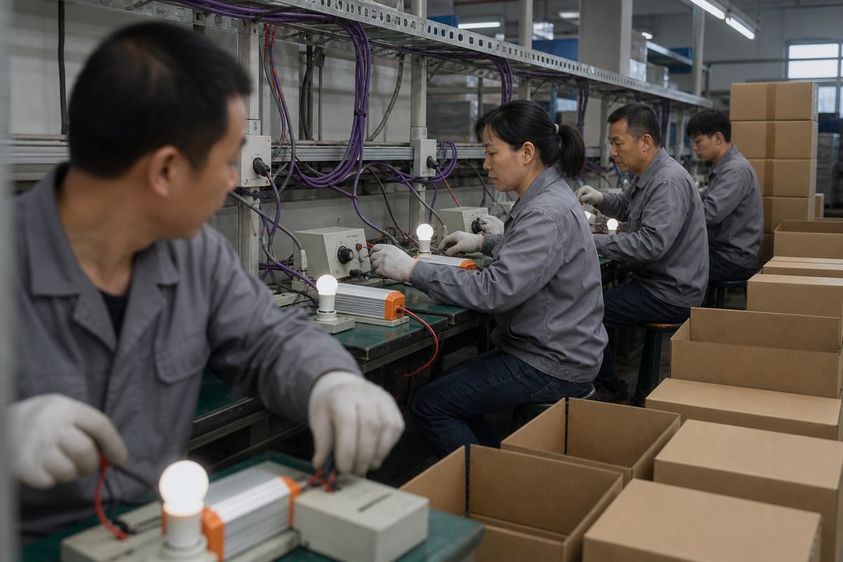
สมมติฐานที่อันตรายในธุรกิจนี้ง่ายมาก: หากผลิตภัณฑ์ทั้งสองระบุว่า 0–10V แสดงว่าเข้ากันได้ ซึ่งไม่จำเป็นเสมอไป ป้าย 0–10V บอกคุณถึงอินเทอร์เฟซแรงดันควบคุม แต่ไม่ได้บอกโทโพโลยี กระแสซอร์ส/ซิงก์ พฤติกรรมขั้ว หรือการใช้งานมาตรฐานที่แน่นอน อุปกรณ์สองตัวที่ไม่ตรงกันสามารถอยู่บนสายสองเส้นเดียวกันและเพียงแค่สื่อสารข้ามกัน เกิดช่วงการหรี่แสงที่ผิดหรือไม่ตอบสนองเลย.
คำนวณ Sink Current
ในเครือข่ายแบบซิงก์ ดriver ทุกตัวที่เพิ่มแบบขนานจะส่งกระแสซอร์สของตัวเองเข้าสู่ลูป คอนโทรลเลอร์ต้องกระจายผลรวมของกระแสทั้งหมดนั้นเพื่อดึงสายลงเป็น 0V ดังนั้นอย่าเพียงแค่นับจำนวนดriver คำนวณ:
กระแสซิงก์รวม ≈ จำนวนดriver × กระแสซอร์สของดriver
จากนั้นเปรียบเทียบตัวเลขนั้นกับความสามารถในการซิงก์ที่ระบุของคอนโทรลเลอร์ ซึ่งวัดเป็น mA นี่คือตัวอย่างการคำนวณพร้อมตัวเลขประกอบ:
| ดriver บนลูป | กระแสซอร์สรวม (ที่ 1 mA ต่อตัว ตัวอย่าง) | คอนโทรลเลอร์รองรับการซิงก์ 5 mA | คอนโทรลเลอร์รองรับการซิงก์ 30 mA |
|---|---|---|---|
| 1 | 1 มิลลิแอมป์ | ทำงานได้ | ทำงานได้ |
| 5 | 5 มิลลิแอมป์ | ใกล้ขีดจำกัด เส้นโค้งผิดเพี้ยน | ทำงานได้ |
| 10 | 10 มิลลิแอมป์ | ไม่สามารถถึงระดับต่ำสุด | ทำงานได้ |
นี่คือสิ่งที่เกิดขึ้นในการนำร่องที่สิงคโปร์: ดriver หนึ่งตัวหรี่แสงได้สมบูรณ์แบบ แต่ดriver สิบตัวเกินความสามารถในการซิงก์ของคอนโทรลเลอร์ ดังนั้นสายจึงไม่สามารถถูกดึงลงต่ำพอได้.
รายละเอียดการเดินสายที่อาจทำให้เกิดปัญหา
นอกเหนือจากคณิตศาสตร์ ดูสี่สิ่งนี้ ประการแรก ขั้วสัญญาณ: 0–10V เป็นสัญญาณ DC แบบมีขั้ว และการกลับขั้ว DIM+ และ DIM− จะป้องกันการหรี่แสงหรืออาจทำให้คอนโทรลเลอร์เสียหาย ประการที่สอง แรงดันตกบนสายควบคุมระยะไกล ซึ่งจะบีบช่วงการหรี่แสงของคุณอย่างเงียบ ๆ ประการที่สาม การกราวด์: คอมมอนลอยในดriver แบบซิงก์อาจทำให้เกิดการกะพริบเมื่อกราวด์สัญญาณควบคุมเคลื่อนออกจากค่าอ้างอิงภายในของดriver ประการที่สี่ คอนโทรลเลอร์ 0–10V ไร้สายสมัยใหม่มักเก็บพลังงานทำงานจากกระแสซอร์สของดriver ดังนั้นจึงทำงานได้กับดriver แบบซอร์สซิ่งจริงเท่านั้น.
ก่อนที่คุณจะเชื่อมต่ออะไร ตรวจสอบรายการนี้:
- ระบุโทโพโลยี: ซอร์สหรือซิงก์?
- ตรวจสอบกระแสซอร์ส: ดriver แต่ละตัวให้กี่ mA?
- ตรวจสอบความสามารถในการซิงก์: คอนโทรลเลอร์ดูดซับได้กี่ mA?
- ตรวจสอบขั้ว: ยืนยัน DIM+ และ DIM−.
- ตรวจสอบมาตรฐาน: อย่าถือว่าอินเทอร์เฟซ 0–10V ทุกตัวทำงานเหมือนกัน.
- ตรวจสอบเอาต์พุตต่ำสุด: ยืนยันสิ่งที่ดriver ทำจริงที่ 0V ไม่ใช่สิ่งที่เอกสารข้อมูลเรียกว่า 0%.
- ทดสอบชุดประกอบทั้งหมด: คอนโทรลเลอร์ จำนวนดriver จริง และโหลด LED จริง.
ฉันจะเลือกซัพพลายเออร์ไดรเวอร์ LED ที่เชื่อถือได้สำหรับระบบ 0–10V แบบ current source หรือ current sink ได้อย่างไร?
สองทศวรรษในอุตสาหกรรมนี้สอนบทเรียนสำคัญแก่ฉัน: ผู้ซื้อไม่ค่อยเสียใจที่ถามคำถามทางเทคนิคที่ยาก แต่พวกเขามักเสียใจที่ถือว่าเอกสารข้อมูลบอกเรื่องราวทั้งหมด.
เลือกซัพพลายเออร์ที่เผยแพร่ค่าพิกัดกระแสซอร์สและซิงก์ ระบุว่าอินเทอร์เฟซ 0–10V แต่ละตัวเป็นไปตามมาตรฐานใด ทดสอบชุดคอนโทรลเลอร์ร่วมกับไดรเวอร์ในปริมาณจริง และให้การสนับสนุนด้านวิศวกรรมแบบ OEM/ODM พันธมิตรที่เชื่อถือได้จะตรวจสอบช่วงการหรี่แสงทั้งหมดก่อนจัดส่ง ไม่ใช่เพียงแค่ฉลาก 0–10V บนเอกสารข้อมูลเท่านั้น.
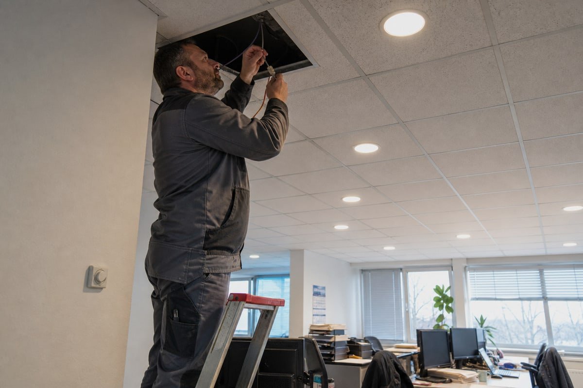
คำถามเรื่องความเข้ากันได้ที่แท้จริงไม่เคยใช่ "ทั้งสองผลิตภัณฑ์เป็น 0–10V หรือไม่?" แต่คือ "คอนโทรลเลอร์ตัวนี้สามารถขับไดรเวอร์จำนวนเท่านี้ได้ทางไฟฟ้าตลอดช่วงการหรี่ไฟที่ต้องการทั้งหมดหรือไม่?" ซัพพลายเออร์ที่ไม่สามารถตอบคำถามนั้นเกี่ยวกับผลิตภัณฑ์ของตนเองได้ จะปล่อยให้คุณเป็นคนหาคำตอบระหว่างการติดตั้งระบบ ด้วยค่าใช้จ่ายของคุณและภายในกำหนดเวลาของคุณ.
นี่คือกรอบการประเมินที่ผมแนะนำให้ลูกค้าตัวแทนจำหน่ายและแบรนด์ส่วนตัวของเราใช้ เพราะเป็นกรอบเดียวกับที่เราใช้กับตัวเอง:
| สิ่งที่ควรถาม | สัญญาณที่ดี | สัญญาณที่ควรระวัง |
|---|---|---|
| อินเทอร์เฟซรองรับมาตรฐานใด? | ระบุ IEC 60929 Annex E, ANSI C137.1 หรือ E1.3 อย่างชัดเจน | ระบุเพียง "0–10V มาตรฐาน" |
| สเปคกระแส source/sink เป็นเท่าใด? | เผยแพร่ค่ามิลลิแอมป์สำหรับทั้งสองบทบาท | ระบุเฉพาะช่วงแรงดันไฟฟ้า |
| คุณสามารถทดสอบชุดค่าผสมที่แน่นอนของฉันได้หรือไม่? | ทดสอบบนโต๊ะ: คอนโทรลเลอร์ + จำนวน + โหลด | "น่าจะใช้งานได้" |
| เกิดอะไรขึ้นที่ 0V? | ระบุพฤติกรรมเอาต์พุตขั้นต่ำจริง | พูดซ้ำ "0%" โดยไม่มีบริบท |
| ใบรับรองและเครื่องหมาย? | CE, CB, SAA, SELV มองเห็นได้บนฉลาก | เครื่องหมายคลุมเครือหรือขาดหายไป |
| การสนับสนุนการปรับแต่ง? | การพัฒนา OEM/ODM, การพิมพ์โลโก้, การติดฉลากขั้วต่อ | ขายเฉพาะแคตตาล็อก |
ในสายการผลิตของเรา ไดรเวอร์ทุกตัวจัดส่งในตัวเรือนอะลูมิเนียมพร้อมครีบระบายความร้อนและขั้วต่อ L, N, LED และ 0–10V ที่พิมพ์อย่างชัดเจน เนื่องจากฉลากสายไฟที่คลุมเครือทำให้เกิดข้อผิดพลาดขั้วไฟฟ้าในภาคสนามในสัดส่วนที่น่าตกใจ ก่อนที่ชุดผลิตภัณฑ์จะออกจากโรงงานไปยังสิงคโปร์ ญี่ปุ่น เยอรมนี หรือออสเตรเลีย เราจะทดสอบคอนโทรลเลอร์ที่ลูกค้าระบุกับจำนวนไดรเวอร์จริงและโหลด LED จริงตลอดช่วงการหรี่แสงทั้งหมด เมื่อลูกค้าในฝรั่งเศสต้องการไดรเวอร์แบบ sinking ที่จับคู่กับไดรเวอร์จากแหล่งที่มาบุคคลที่สาม วิศวกรของเราขอสเปคกระแส source ของไดรเวอร์นั้นก่อน แล้วจึงออกแบบขั้นตอน sink ให้เหมาะสมกับค่านั้น นี่คือระดับความละเอียดที่ควรเรียกร้องจากพันธมิตรทุกคน รวมถึงเราเองด้วย เพราะมันปกป้องต้นทุนโครงการ กำหนดส่งมอบ และชื่อแบรนด์ของคุณบนกล่อง.
บทสรุป
กระแส source เทียบกับกระแส sink ในระบบ 0–10V เป็นคำถามเรื่องความเข้ากันได้ ไม่ใช่แค่ฉลาก จับคู่โทโพโลยี ตรวจสอบความสามารถของ sink และทดสอบชุดค่าผสมทั้งหมดก่อนที่ไดรเวอร์จะจัดส่ง.
เชิงอรรถ
โปรแกรมมาตรฐานทางเทคนิคของ ESTA ดูแลมาตรฐาน ANSI E1.3 สำหรับการควบคุม 0-10V ในโรงละคร. ↩︎
เว็บสโตร์ของคณะกรรมการอิเล็กโทรเทคนิคระหว่างประเทศให้มาตรฐาน IEC 60929 อย่างเป็นทางการสำหรับการควบคุมแสงสว่าง. ↩︎
เว็บไซต์อย่างเป็นทางการของ NEMA หน่วยงานที่รับผิดชอบมาตรฐานอินเทอร์เฟซแสงสว่าง ANSI C137.1. ↩︎
อธิบายธรรมชาติของสัญญาณกระแสตรงที่ขั้วไฟฟ้าเป็นปัจจัยสำคัญ. ↩︎
คำนิยามทางเทคนิคของโพเทนชิโอมิเตอร์ ซึ่งใช้เป็น sink แบบพาสซีฟในวงจรหรี่แสงแบบแอนะล็อก. ↩︎