














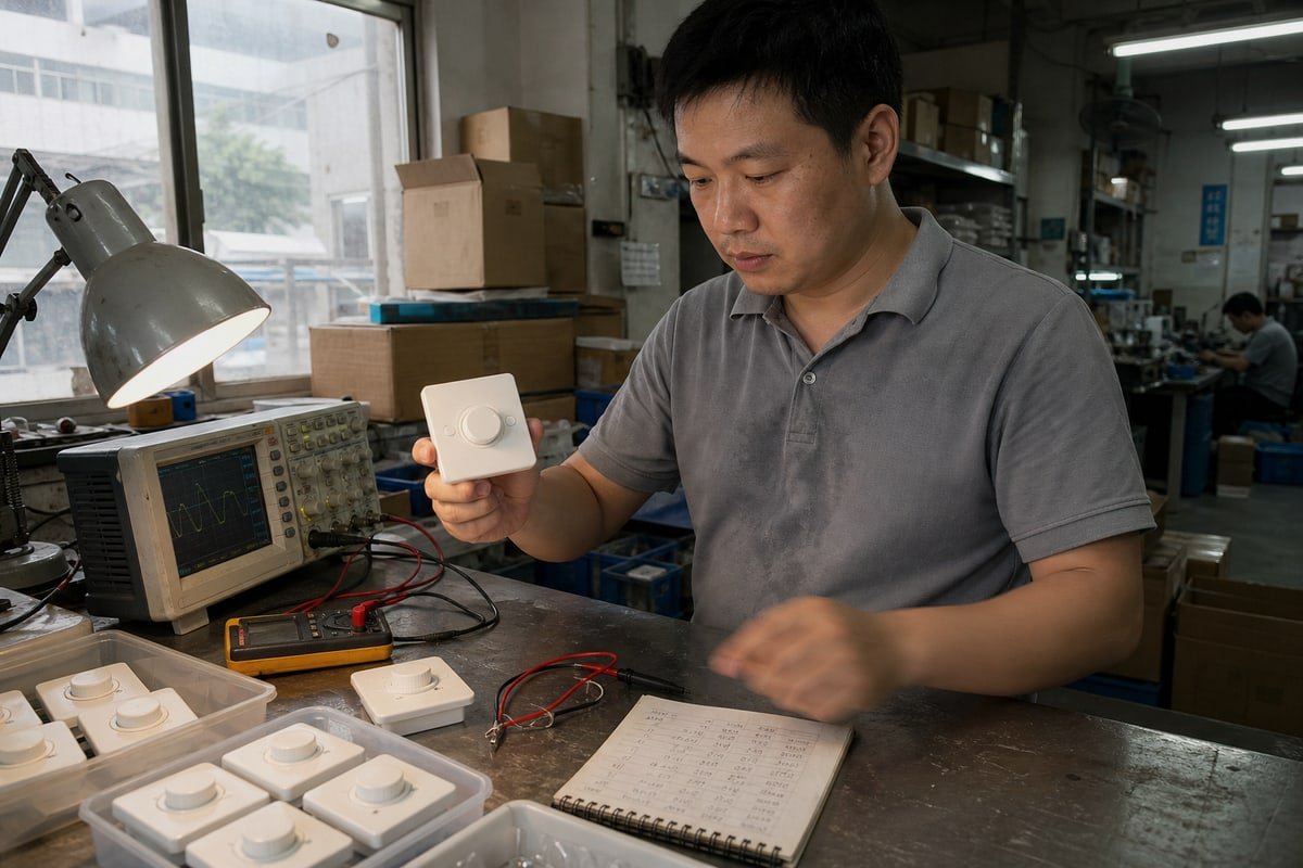
ตัวหรี่แสงแบบ trailing edge สัญญาว่าจะควบคุม LED ได้อย่างราบรื่น แต่การกะพริบและเสียงรบกวนยังคงทำให้โปรเจกต์เสียหายเมื่อใช้งานไม่ตรงกัน บนสายการผลิตที่เซินเจิ้นของเรา เราทดสอบกับความล้มเหลวนั้นทุกวัน.
ตัวหรี่แสงแบบ trailing edge คือตัวหรี่แสงไฟฟ้ากระแสสลับแบบอิเล็กทรอนิกส์ที่ลดความสว่างโดยการตัดกระแสไฟฟ้าใกล้จุดสิ้นสุดของแต่ละครึ่งรอบของรูปคลื่นไฟฟ้ากระแสสลับ หรือที่เรียกว่าการหรี่แสงแบบ reverse phase ใช้อุปกรณ์สวิตช์ MOSFET และเหมาะกับไดรเวอร์ LED สมัยใหม่ออกแบบมาสำหรับวิธีตัดเฟสนี้.
คำจำกัดความนั้นเป็นเพียงจุดเริ่มต้นเท่านั้น เรื่องจริงคือรูปคลื่นถูกตัดอย่างไร แตกต่างจากการออกแบบรุ่นเก่าอย่างไร และเหตุใดไดรเวอร์ LED จึงเป็นตัวตัดสินว่าผลลัพธ์ดูเป็นมืออาชีพหรือไม่ ให้ฉันอธิบายแต่ละส่วนให้คุณฟัง.
ตัวหรี่แสงแบบ trailing edge ทำงานอย่างไรจริง?
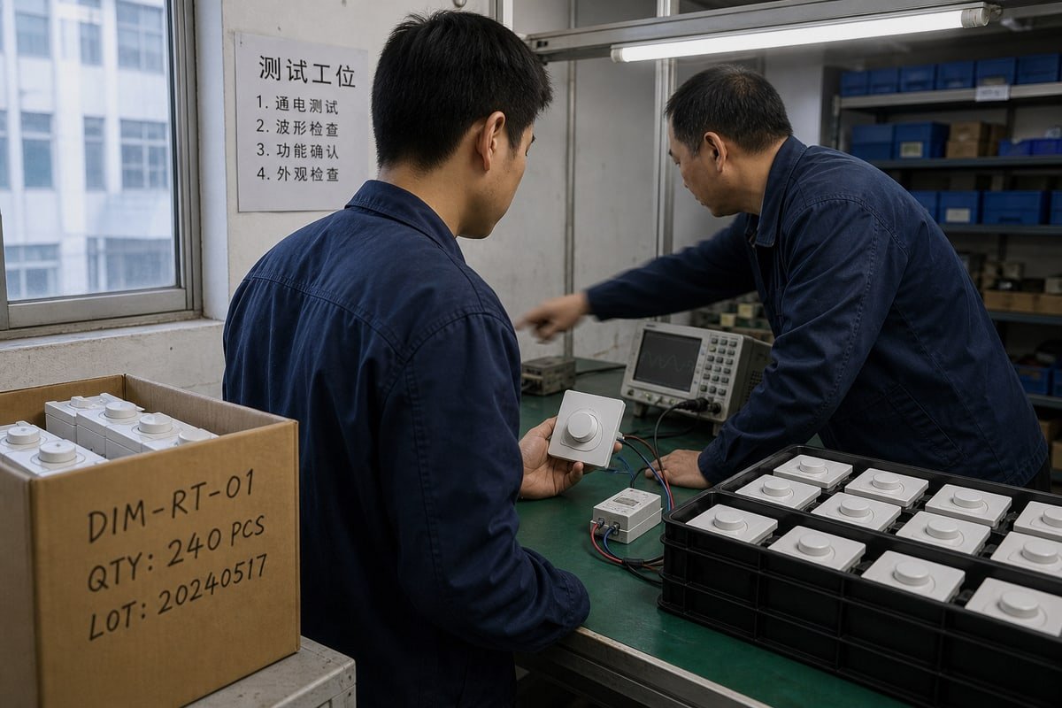
เดือนที่แล้ววิศวกรของเราตรวจสอบชุดตัวหรี่แสงแบบหมุนก่อนจัดส่งไปอิตาลี การสังเกตรูปคลื่นยุบตัวอย่างนุ่มนวลที่ปลายแต่ละรอบอธิบายเทคโนโลยีนี้ได้ดีกว่าเอกสารข้อมูลใดๆ.
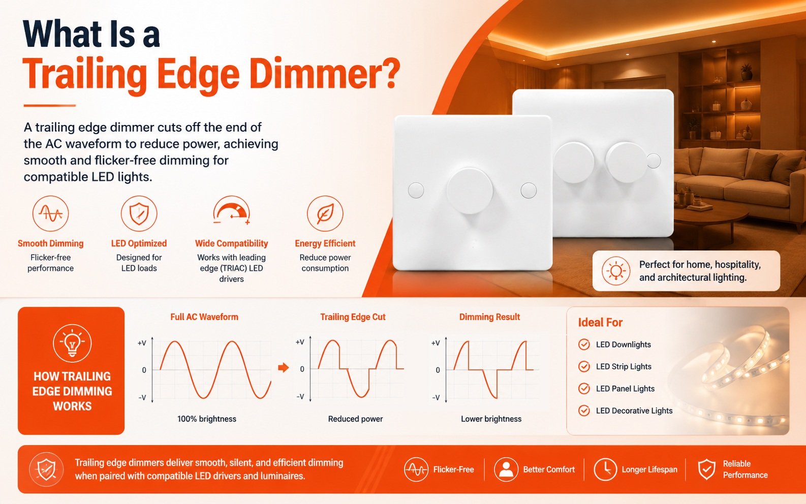
ตัวหรี่แสงแบบ trailing edge ให้แต่ละครึ่งรอบของไฟฟ้ากระแสสลับเริ่มต้นตามปกติ จากนั้น MOSFET จะตัดกระแสไฟฟ้าก่อนถึงจุดตัดศูนย์ การตัดส่วนท้ายของรูปคลื่นมากขึ้นจะลดความสว่างลง การตัดน้อยลงจะเพิ่มความสว่าง ไดรเวอร์ LED จะแปลงรูปคลื่นที่ถูกตัดนี้เป็นเอาต์พุตที่หรี่แสงได้.
ไฟฟ้าหลักมาถึงเป็นคลื่นไซน์ที่ซ้ำกัน แต่ละคลื่นมีสองครึ่งรอบ และทุกครึ่งรอบเริ่มต้นและสิ้นสุดที่จุดตัดศูนย์ ตัวหรี่แสงแบบ trailing edge ทำงานบนโครงสร้างนั้น ปล่อยให้กระแสไฟฟ้าไหลตั้งแต่ช่วงที่ครึ่งรอบเริ่มต้น จากนั้น ณ จุดที่กำหนดเวลาอย่างแม่นยำ จะตัดกระแสไฟฟ้าก่อนที่ครึ่งรอบจะสิ้นสุด นี่คือเหตุผลที่เทคนิคนี้เรียกว่า การหรี่แสงแบบ reverse phase. สายสัญญาณนั้นง่าย: รูปคลื่นไฟฟ้ากระแสสลับ → การตัดเฟสแบบ trailing-edge → ไดรเวอร์ LED → เอาต์พุตแสงที่ควบคุมได้.
ทำไมเทคโนโลยี MOSFET จึงสำคัญที่นี่
การออกแบบการตัดเฟสรุ่นเก่าอาศัย TRIAC ซึ่งล็อกเปิดและปิดอย่างฉับพลัน หน่วยแบบ trailing edge ใช้ เทคโนโลยี MOSFET 1 หรือ IGBT แทน อุปกรณ์สวิตช์เซมิคอนดักเตอร์เหล่านี้ช่วยให้การปิดเป็นไปอย่างควบคุมและค่อยเป็นค่อยไป กระแสไฟฟ้าลดลงตามธรรมชาติสู่ศูนย์แทนที่จะถูกตัดอย่างรุนแรง การลดลงอย่างนุ่มนวลนั้นป้องกันความเสียหายจาก back-EMF ในวงจรหม้อแปลงอิเล็กทรอนิกส์ที่ไวต่อการเปลี่ยนแปลง และลดแรงดันไฟฟ้ากระชากบนสาย.
ลำดับการตัดเฟส ทีละขั้นตอน
| ขั้นตอน | สิ่งที่เกิดขึ้น | ผลต่อแสง |
|---|---|---|
| จุดตัดศูนย์ | ครึ่งรอบเริ่มต้น กระแสไฟฟ้าไหลตามปกติ | การจ่ายพลังงานเริ่มต้น |
| ช่วงการนำไฟฟ้า | รูปคลื่นผ่านโดยไม่มีการปรับเปลี่ยน | พลังงานถึงไดรเวอร์ |
| การปิดหน่วงเวลา | MOSFET ตัดกระแสก่อนสิ้นสุดรอบคลื่น | ความสว่างถูกกำหนดด้วยจังหวะเวลา |
| การลดลงสู่ศูนย์ | กระแสลดลงอย่างนุ่มนวลจนถึงจุดตัดศูนย์ถัดไป | ความเครียดต่ำ เสียงรบกวนต่ำ |
ตัวหรี่แสงแบบตัดขอบท้ายหลายรุ่นยังมีฟีเจอร์สตาร์ทแบบนุ่มนวล (soft start) แทนที่จะจ่ายไฟเต็มกำลังให้หลอดไฟในทันทีที่เปิดสวิตช์ กลับค่อยๆ เพิ่มกำลังไฟอย่างค่อยเป็นค่อยไป จากการทดสอบของเราเอง วิธีนี้ช่วยปกป้องชิ้นส่วน LED จากความร้อนช็อกและยืดอายุการใช้งานของหลอดไฟในรอบการสลับเปิดปิดซ้ำๆ.
ความแตกต่างระหว่างตัวหรี่แสงแบบ trailing edge และ leading edge คืออะไร?
ผู้จัดการฝ่ายจัดซื้อในสิงคโปร์เคยถามฉันว่าทำไมสต็อกตัวหรี่แสงแบบตัดขอบหน้าของเธอจึงเกิดเสียงหึ่งเมื่อใช้กับหลอด LED รีโทรฟิต คำตอบอยู่ที่ว่าการออกแบบแต่ละแบบตัดส่วนใดของรูปคลื่น.
ตัวหรี่แสงแบบตัดขอบหน้าตัดส่วนหน้าของแต่ละครึ่งรอบไฟฟ้ากระแสสลับโดยใช้ TRIAC เหมาะกับโหลดความต้านทานแบบหลอดไส้และฮาโลเจน ตัวหรี่แสงแบบตัดขอบท้ายตัดส่วนท้ายโดยใช้ MOSFET เหมาะกับโหลดแบบคาปาซิทีฟ LED และโหลดอิเล็กทรอนิกส์ ไม่มีแบบใดดีกว่าแบบอื่นโดยสิ้นเชิง สเตจอินพุตของไดรเวอร์ที่เชื่อมต่ออยู่เป็นตัวกำหนดตัวเลือกที่ถูกต้อง.
นี่คือการเปรียบเทียบโดยสรุป:
| ลักษณะเฉพาะ | ตัวหรี่แสงแบบตัดขอบหน้า | ตัวหรี่แสงแบบตัดขอบท้าย |
|---|---|---|
| ตำแหน่งการตัด | ส่วนหน้าของแต่ละครึ่งรอบ | ปลายของแต่ละครึ่งรอบ |
| ชื่อเรียกอื่น | ฟอร์เวิร์ดเฟส, การหรี่แสงแบบไทรแอก | การหรี่แสงแบบรีเวิร์สเฟส |
| ชิ้นส่วนสวิตช์ | ไทรแอก | MOSFET หรือ IGBT |
| พฤติกรรมการเปิด/ปิด | ขั้นแรงดันไฟฟ้าที่ฉับพลันและคมชัด | การลดลงอย่างนุ่มนวลและค่อยเป็นค่อยไปจนถึงศูนย์ |
| โหลดที่เหมาะสมที่สุด | ความต้านทานแบบหลอดไส้, ฮาโลเจน | โหลดแบบคาปาซิทีฟ, ไดรเวอร์ LED, ELV |
| ข้อกำหนดโหลดขั้นต่ำ | สูงกว่า | ต่ำกว่าอย่างมีนัยสำคัญ |
| เสียงรบกวนที่ได้ยิน | มีแนวโน้มเกิดเสียงหึ่งจากแรงดันไฟฟ้าสไปก์ | โดยทั่วไปเงียบ |
| เสียงรบกวนในสายไฟ | ฮาร์มอนิกดิสทอร์ชันสูงกว่า | ค่า THD และเสียงรบกวนทางไฟฟ้าลดลง |
การเปิดที่ฉับพลันของ TRIAC สร้างแรงดันไฟฟ้าสไปก์ที่สูงชันในทุกครึ่งรอบ บน หม้อแปลงแม่เหล็ก 2 และหลอดไส้เส้นใย สไปก์นั้นไม่เป็นอันตราย แต่บนโหลดแบบคาปาซิทีฟ เช่น ฟิลเตอร์อินพุตของไดรเวอร์ LED จะเกิดกระแสไหลเข้าสูง (inrush current) กระแสไหลเข้านี้คือต้นเหตุของเสียงหึ่ง การกะพริบระริก และอายุการใช้งานชิ้นส่วนที่สั้นลงที่ลูกค้าชาวสิงคโปร์ของฉันพบเห็น การออกแบบแบบตัดขอบท้ายหลีกเลี่ยงสไปก์โดยสิ้นเชิง ซึ่งยังช่วยลด ฮาร์มอนิกดิสทอร์ชันรวม 3 ในวงจรไฟฟ้าท้องถิ่นอีกด้วย.
มีความแตกต่างเชิงปฏิบัติอีกประการที่เราเน้นย้ำกับตัวแทนจำหน่ายทุกครั้ง: โหลดขั้นต่ำ ตัวหรี่แสงแบบตัดขอบหน้าต้องการโหลดความต้านทานที่มากพอเพื่อให้ TRIAC นำกระแสได้อย่างต่อเนื่อง ตัวหรี่แสงแบบตัดขอบท้ายรักษาช่วงการหรี่แสงที่เสถียรด้วยวัตต์ที่ต่ำกว่ามาก ซึ่งสำคัญเมื่อห้องหนึ่งใช้ดาวน์ไลท์ LED วัตต์ต่ำเพียงไม่กี่ดวง.
ข้อควรระวังจากมุมมองการออกแบบ: นี่ไม่ใช่เพียงแค่เทคโนโลยีเก่ากับเทคโนโลยีใหม่เท่านั้น การติดตั้งบางแห่งที่มีหม้อแปลงแม่เหล็กรุ่นเก่าจำเป็นต้องใช้การควบคุมแบบลีดดิ้งเอดจ์ การเลือกที่ถูกต้องขึ้นอยู่กับคุณลักษณะทางไฟฟ้าของไดรเวอร์ที่เชื่อมต่อ รวมถึงพฤติกรรมของกระแสไฟฟ้าขาเข้าและข้อกำหนดโหลดขั้นต่ำ.
ไดรเวอร์ LED ใดที่เข้ากันได้กับตัวหรี่แสงแบบ trailing edge?
ในช่วงแรกของธุรกิจส่งออก เราได้เรียนรู้บทเรียนที่มีค่า: ดิมเมอร์ที่ผ่านการทดสอบบนโต๊ะทุกครั้งกลับกะพริบกับดาวน์ไลท์แบรนด์ส่วนตัวของลูกค้า สเตจอินพุตของไดรเวอร์คือตัวกำหนดที่แท้จริง.
ไดรเวอร์ LED ที่เข้ากันได้กับทราเอดิ้งเอดจ์ดิมเมอร์คือไดรเวอร์แบบเฟสคัทที่หรี่แสงได้ซึ่งระบุอย่างชัดเจนว่ารองรับการควบคุมแบบทราเอดิ้งเอดจ์หรือรีเวิร์สเฟส ตรวจสอบวิธีการหรี่แสง โหลดขั้นต่ำ โหลดสูงสุด และช่วงการหรี่แสงที่ระบุในไดรเวอร์ และยืนยันการจับคู่กับรายการความเข้ากันได้ที่ผ่านการทดสอบของผู้ผลิตก่อนซื้อ.

ความผิดพลาดที่ใหญ่ที่สุดที่ผู้ซื้อทำคือการเลือกดิมเมอร์โดยพิจารณาจากสเปกของดิมเมอร์เพียงอย่างเดียว จากประสบการณ์ของเราในการพัฒนาไดรเวอร์ LED แบบหรี่แสงได้ควบคู่กับตัวดิมเมอร์เอง สเตจอินพุตของไดรเวอร์ LED คือตัวกำหนดความเข้ากันได้ที่แท้จริง ไดรเวอร์ประกอบด้วยเรกติไฟเออร์ ตัวกรอง EMI 4, ตัวเก็บประจุ และวงจรสวิตชิ่ง เมื่อขอบท้ายของรูปคลื่นไฟฟ้ากระแสสลับถูกตัดออก ส่วนประกอบเหล่านี้จะกำหนดว่าไดรเวอร์ตอบสนองอย่างไร ไดรเวอร์สองตัวที่มีพิกัดกำลังวัตต์เท่ากันสามารถทำงานแตกต่างกันโดยสิ้นเชิงกับวอลคอนโทรลตัวเดียวกัน.
การผสมผสานที่เข้ากันไม่ได้ยังคงทำให้เกิดความล้มเหลวในโลกแห่งความเป็นจริง แม้ว่าผลิตภัณฑ์ทั้งสองจะยอดเยี่ยมเป็นรายบุคคลก็ตาม:
- การกะพริบที่ความสว่างต่ำ
- ช่วงการหรี่แสงที่จำกัด
- การดับก่อนที่ดิมเมอร์จะถึงระดับต่ำสุด
- การกระพริบเมื่อเปิดเครื่อง
- เสียงรบกวนที่ได้ยิน
- พฤติกรรมที่ไม่สม่ำเสมอระหว่างโหลด LED ที่แตกต่างกัน
รายการตรวจสอบความเข้ากันได้ของ LED ในทางปฏิบัติ
| ตรวจสอบ | สิ่งที่ต้องตรวจสอบ | เหตุใดจึงสำคัญ |
|---|---|---|
| วิธีการหรี่แสง | ดาต้าชีตไดรเวอร์ระบุการรองรับทราเอดิ้งเอดจ์ / รีเวิร์สเฟส | ไดรเวอร์บางตัวรองรับเฉพาะการหรี่แสงแบบ TRIAC หรือสัญญาณ 0–10V เท่านั้น |
| โหลดขั้นต่ำ | กำลังวัตต์รวมของโคมไฟเกินค่าขั้นต่ำของดิมเมอร์ | ต่ำกว่าค่าขั้นต่ำ วงจรจะทำงานผิดพลาดและสั่นไหว |
| โหลดสูงสุด | กำลังวัตต์รวมอยู่ต่ำกว่าเพดานที่กำหนด | การโอเวอร์โหลดทำให้อายุการใช้งานของ MOSFET สั้นลง |
| ช่วงการหรี่แสง | ค่าเปอร์เซ็นต์ต่ำสุดที่เผยแพร่ตรงกับความต้องการของโครงการ | กำหนดว่าการหรี่แสงลึกแค่ไหนก่อนที่จะดับ |
| รายการความเข้ากันได้ | การจับคู่ดิมเมอร์–ไดรเวอร์ที่แน่นอนได้รับการยืนยันแล้ว | คู่ที่ผ่านการทดสอบบนโต๊ะเท่านั้นที่เป็นหลักฐานที่เชื่อถือได้ |
เมื่อเราดำเนินโครงการ OEM ให้กับแบรนด์ไฟส่องสว่าง เราทดสอบรุ่นไดรเวอร์ที่แน่นอนกับดิมเมอร์ที่แน่นอนก่อนการผลิตจำนวนมาก มันช้ากว่าการเชื่อถือดาต้าชีต แต่มันเป็นวิธีเดียวที่จะรับประกันความเข้ากันได้ของ LED ทั่วทั้งสายผลิตภัณฑ์ ซึ่งเป็นเหตุผลที่เราสร้างรายการคู่ที่ผ่านการทดสอบในทุกโครงการพัฒนาร่วมกัน.
ทำไมฉันควรเลือกตัวหรี่แสงแบบ trailing edge สำหรับโปรเจกต์แสงสว่างของฉัน?
ทุกใบเสนอราคาที่เราเตรียมชั่งน้ำหนักระหว่างต้นทุนกับประสิทธิภาพ ทราเอดิ้งเอดจ์ยูนิตมีต้นทุนสูงกว่า การหรี่แสงแบบ TRIAC รุ่นพื้นฐาน แต่จำนวนข้อร้องเรียนที่น้อยกว่ามักจะพิสูจน์ความแตกต่างในโครงการ LED.
เลือกทราเอดิ้งเอดจ์ดิมเมอร์สำหรับโครงการ LED เพราะให้การทำงานที่เงียบกว่า การหรี่แสงช่วงต่ำที่ราบรื่นกว่า ข้อกำหนดโหลดขั้นต่ำที่ต่ำกว่า การป้องกันซอฟต์สตาร์ท และเสียงรบกวนทางไฟฟ้าที่ลดลง ตรวจสอบความเข้ากันได้ของไดรเวอร์ก่อนเสมอ เนื่องจากประโยชน์เหล่านี้จะปรากฏเฉพาะเมื่อดิมเมอร์และไดรเวอร์จับคู่กันอย่างถูกต้อง.

สำหรับผู้จัดจำหน่ายและบริษัทวิศวกรรม เหตุผลในการใช้การควบคุมแบบทราเอดิ้งเอดจ์ขึ้นอยู่กับพฤติกรรมที่วัดได้มากกว่าฉลากทางการตลาด เมื่อดิมเมอร์และไดรเวอร์จับคู่กันอย่างเหมาะสม ประโยชน์จะสะสมอย่างรวดเร็ว การหรี่แสงช่วงต่ำจะราบรื่นแทนที่จะเป็นขั้นบันได เสียงฮัมที่ได้ยินจะหายไปเพราะไม่มี แรงดันไฟฟ้ากระชากของ TRIAC มาสั่นสะเทือนส่วนประกอบ โหลดอิเล็กทรอนิกส์กำลังวัตต์ต่ำคงความเสถียร ซึ่งสำคัญเมื่อโคมไฟมีขนาดเล็กลงเรื่อยๆ และฟีเจอร์ซอฟต์สตาร์ทจะค่อยๆ เพิ่มกำลังไฟอย่างนุ่มนวล ปกป้องหลอดไฟจากความร้อนช็อกทุกครั้งที่เปิดเครื่อง.
ปรากฏการณ์ Ghosting และแสงเรืองเมื่อปิด
ปัญหาหนึ่งที่เราแก้ไขอยู่ตลอดในโครงการ ODM คือโกสติ้ง การเรืองแสงจางๆ ของ LED ในสถานะปิด การออกแบบทราเอดิ้งเอดจ์คุณภาพจัดการปัญหานี้ผ่านการรวมชันท์คาปาซิเตอร์ ซึ่งช่วยระบายกระแสรั่วไหลที่ตกค้างซึ่งทำให้ไดรเวอร์ที่ไวต่อความรู้สึกยังคงได้รับพลังงานเล็กน้อย หากสต็อกปัจจุบันของคุณเรืองแสงเมื่อปิด นี่คือวิธีแก้ไขที่ควรระบุ.
การวางแผนการติดตั้ง: การลดพิกัดแบบหลายช่อง
มีสเปกหนึ่งที่ทำให้แม้แต่ช่างติดตั้งที่มีประสบการณ์สะดุด เมื่อโมดูลดิมเมอร์หลายตัวใช้กล่องผนังแบบหลายแก๊งร่วมกัน ความร้อนจะสะสมและแต่ละยูนิตต้องลดพิกัดลง เราออกแบบทั้งแผงหน้าปัดแบบหมุนปุ่มเดียวและสองปุ่ม และเราพิมพ์คำแนะนำการลดพิกัดด้วยเหตุผลนี้พอดี.
| การติดตั้ง | พิกัดกำลังไฟทั่วไป | หมายเหตุการวางแผน |
|---|---|---|
| ยูนิตเดียว กล่องเดียว | โหลดเต็มพิกัด | ใช้สเปกมาตรฐาน |
| สองยูนิต กล่องร่วม | ลดโหลดต่อยูนิต | การลดกำลังไฟฟ้าเป็นสิ่งที่ต้องทำ ไม่ใช่ทางเลือก |
| สามหน่วยหรือมากกว่า | ลดเพิ่มเติมต่อหน่วย | ยืนยันกราฟการลดกำลังไฟฟ้าที่เฉพาะเจาะจง |
สำหรับประสิทธิภาพที่ปราศจากการกะพริบทั่วทั้งโครงการ มุมมอง B2B ของฉันคือเรื่องง่าย อย่าเลือก trailing-edge dimmer เพียงเพราะถูกทำการตลาดว่ารองรับ LED ตรวจสอบวิธีการลดแสงที่ระบุของไดรเวอร์ โหลดขั้นต่ำ โหลดสูงสุด ช่วงการลดแสง และความเข้ากันได้ที่ได้รับการยืนยันกับ dimmer เฉพาะนั้น นั่นคือจุดที่ความแตกต่างระหว่าง dimmer ที่ทำงานได้กับระบบลดแสงที่ทำงานอย่างมืออาชีพมักจะปรากฏขึ้น.
บทสรุป
Trailing edge dimmer ตัดส่วนท้ายของแต่ละครึ่งรอบไฟฟ้ากระแสสลับเพื่อการลดแสง LED ที่เงียบและราบรื่น จับคู่กับไดรเวอร์ที่ได้รับการยืนยัน ทุกโครงการจะทำงานอย่างมืออาชีพ.
เชิงอรรถ
ภาพรวมทางเทคนิคของเทคโนโลยีเซมิคอนดักเตอร์ที่ใช้สำหรับการตัดวงจรแบบควบคุมใน trailing edge dimmers. ↩︎
สมาคมวิชาชีพชั้นนำด้านมาตรฐานวิศวกรรมไฟฟ้าที่เกี่ยวข้องกับหม้อแปลงไฟฟ้าและวงจรไฟฟ้า. ↩︎
แหล่งข้อมูลภาครัฐที่มีอำนาจสำหรับมาตรฐานทางเทคนิคและตัวชี้วัดการวัด เช่น การเพี้ยนฮาร์มอนิก. ↩︎
คำอธิบายทางเทคนิคของตัวกรองสัญญาณรบกวนที่ใช้เพื่อรักษาเสถียรภาพของพลังงานในวงจรไดรเวอร์ LED. ↩︎