















A trailing edge dimmer promises smooth LED control, yet flicker and buzzing still ruin projects when it’s mismatched. On our Shenzhen production line, we test against exactly that failure daily.
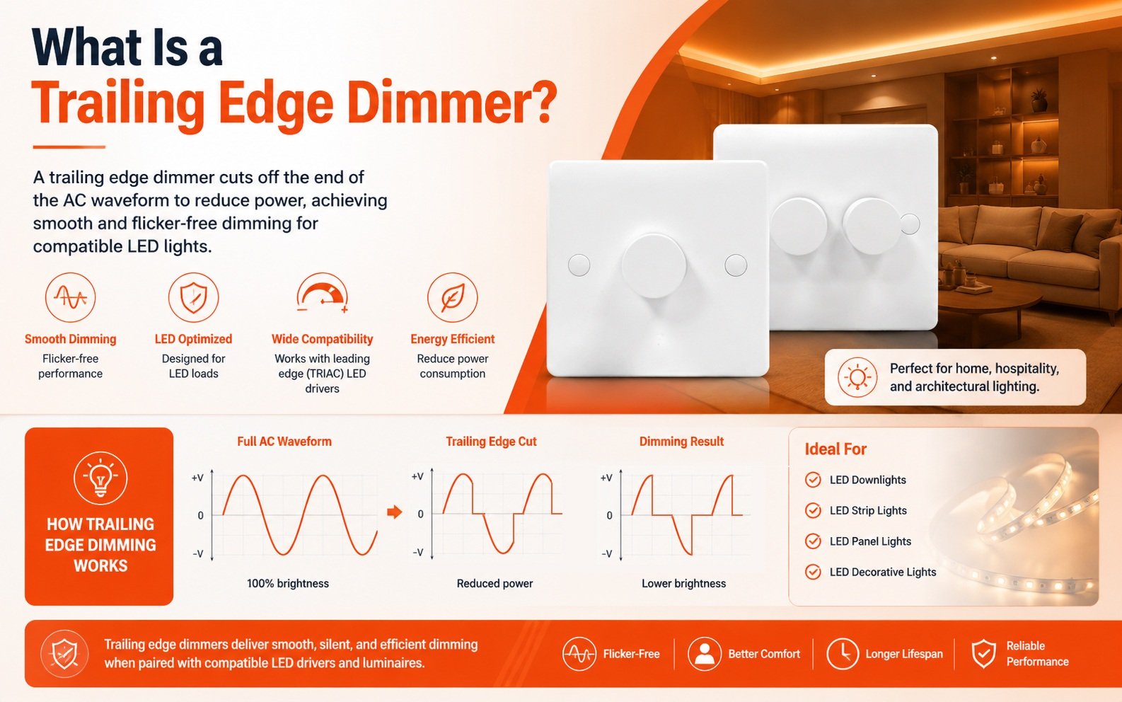
A trailing edge dimmer is an electronic AC dimmer that reduces light output by switching off current near the end of each half-cycle of the AC waveform. Also called reverse phase dimming, it uses MOSFET switches and suits modern LED drivers designed for this phase-cut method.
That definition is only the starting point. The real story is how the waveform gets cut, how this differs from older designs, and why the LED driver decides whether the result looks professional. Let me walk you through each part.
How does a trailing edge dimmer actually work?
Last month our engineers scoped a batch of rotary dimmers before shipment to Italy. Watching the waveform collapse gently at each cycle’s end explains this technology better than any datasheet.
A trailing edge dimmer lets each AC half-cycle begin normally, then a MOSFET switches the current off before the zero crossing. Cutting more of the waveform’s tail lowers light output; cutting less raises it. The LED driver converts this chopped waveform into a dimmed output.

Mains electricity arrives as a repeating sine wave. Each wave has two half-cycles, and every half-cycle starts and ends at a zero crossing. A trailing edge dimmer works on that structure. It allows current to flow from the moment the half-cycle begins. Then, at a precisely timed point, it switches the current off before the half-cycle finishes. This is why the technique is called reverse phase dimming. The signal chain is simple: AC waveform → trailing-edge phase cut → LED driver → controlled light output.
Why MOSFET technology matters here
Older phase-cut designs rely on TRIACs, which latch on and snap off abruptly. Trailing edge units use MOSFET technology 1 or IGBTs instead. These semiconductor switches allow a controlled, gradual turn-off. The current decays naturally toward zero rather than being chopped violently. That gentle decay prevents back-EMF damage in sensitive electronic transformer circuits and reduces voltage spikes on the line.
The phase-cut sequence, step by step
| Stage | What happens | Effect on light |
|---|---|---|
| 1. Zero crossing | Half-cycle begins, current flows normally | Power delivery starts |
| 2. Conduction period | Waveform passes through unmodified | Energy reaches the driver |
| 3. Timed switch-off | MOSFET interrupts current before the cycle ends | Brightness is set by the timing |
| 4. Decay to zero | Current falls gently to the next zero crossing | Low stress, low noise |
Many trailing edge dimmers also include a soft start feature. Instead of hitting the lamp with full power at switch-on, they ramp up gradually. In our own testing, this protects LED components from thermal shock and extends lamp life across repeated switching cycles.
What’s the difference between trailing edge and leading edge dimmers?
A procurement manager in Singapore once asked me why her leading edge dimmer stock buzzed on LED retrofits. The answer sits in which half of the waveform each design cuts.
Leading edge dimmers cut the front of each AC half-cycle using TRIACs, suiting resistive incandescent and halogen loads. Trailing edge dimmers cut the back using MOSFETs, suiting capacitive LED and electronic loads. Neither is universally better; the connected driver’s input stage determines the right choice.
Here is the comparison at a glance:
| Feature | Leading edge dimmer | Trailing edge dimmer |
|---|---|---|
| Cut position | Front of each half-cycle | End of each half-cycle |
| Also known as | Forward phase, triac dimming | Reverse phase dimming |
| Switching component | TRIAC | MOSFET or IGBT |
| Turn-on/turn-off behavior | Abrupt, sharp voltage step | Gradual, soft decay to zero |
| Best-suited loads | Resistive incandescent, halogen | Capacitive load types, LED drivers, ELV |
| Minimum load requirement | Higher | Significantly lower |
| Audible noise | Prone to buzzing from voltage spikes | Typically silent |
| Line noise | Higher harmonic distortion | Reduced THD and electrical noise |
The abrupt turn-on of a TRIAC creates a steep voltage spike at every half-cycle. On magnetic transformers 2 and filament lamps, that spike is harmless. On a capacitive load such as an LED driver’s input filter, it produces a large inrush current. That inrush is the source of the buzz, the shimmer, and the shortened component life my Singaporean client was seeing. Trailing edge designs avoid the spike entirely, which also reduces total harmonic distortion 3 on the local circuit.
There is a second practical difference we highlight to every distributor: minimum load. Leading edge dimmers need a substantial resistive load to keep the TRIAC conducting reliably. Trailing edge dimmers hold a stable dimming range with far lower wattage, which matters when a room runs on a handful of low-wattage LED downlights.
One caution from the design bench: this is not simply old technology versus new technology. Some installations with legacy magnetic transformers genuinely require leading-edge control. The correct choice depends on the electrical characteristics of the connected driver, including its input current behavior and minimum-load requirements.
Which LED drivers are compatible with a trailing edge dimmer?
Early in our export business we learned an expensive lesson: a dimmer that passed every bench test flickered with a client’s private-label downlights. The driver’s input stage was the gatekeeper.
LED drivers compatible with a trailing edge dimmer are phase-cut dimmable drivers explicitly rated for trailing-edge or reverse-phase control. Check the driver’s specified dimming method, minimum load, maximum load, and dimming range, and confirm the pairing on the manufacturer’s tested compatibility list before purchase.

The biggest mistake buyers make is choosing a dimmer based only on the dimmer’s specifications. In our experience developing dimmable LED drivers alongside the dimmers themselves, the input stage of the LED driver is the real compatibility gatekeeper. A driver contains a rectifier, an EMI filter 4, storage capacitors, and switching circuitry. When the trailing edge of the AC waveform is interrupted, those components determine how the driver responds. Two drivers with identical wattage ratings can behave completely differently on the same wall control.
An incompatible combination can still produce real-world failures, even when both products are individually excellent:
- Flicker at low brightness
- A restricted dimming range
- Dropout before the dimmer reaches minimum
- Flashing when switching on
- Audible noise
- Uneven behavior between different LED loads
A practical LED compatibility checklist
| Check | What to verify | Why it matters |
|---|---|---|
| Dimming method | Driver datasheet states trailing-edge / reverse-phase support | Some drivers only accept triac dimming or 0–10V signals |
| Minimum load | Total fixture wattage exceeds the dimmer’s minimum | Below minimum, the circuit misfires and shimmers |
| Maximum load | Total wattage stays under the rated ceiling | Overload shortens the MOSFET’s life |
| Dimming range | Published low-end percentage matches project needs | Determines how deep the dim goes before dropout |
| Compatibility list | The exact dimmer–driver pairing is verified | Bench-tested pairs are the only reliable proof |
When we run OEM projects for lighting brands, we test the exact driver model against the exact dimmer before mass production. It is slower than trusting a datasheet. It is also the only way to guarantee LED compatibility across an entire product line, which is why we build tested pairing lists into every collaborative development project.
Why should I choose a trailing edge dimmer for my lighting projects?
Every quotation we prepare weighs cost against performance. Trailing edge units cost more than basic triac dimming models, yet fewer complaints usually justify the difference on LED projects.
Choose a trailing edge dimmer for LED projects because it delivers quieter operation, smoother low-end dimming, lower minimum-load requirements, soft start protection, and reduced electrical noise. Always verify driver compatibility first, since these benefits only appear when the dimmer and driver are correctly matched.

For distributors and engineering firms, the case for trailing edge control rests on measurable behavior rather than marketing labels. When the dimmer and driver are properly matched, the benefits stack up quickly. Low-end dimming becomes smooth instead of steppy. The audible buzz disappears because there are no TRIAC voltage spikes to vibrate components. Low-wattage electronic loads stay stable, which matters as fixtures keep shrinking in power. And the soft start feature ramps power up gently, protecting bulbs from thermal shock at every switch-on.
Ghosting and off-state glow
One problem we solve constantly in ODM projects is ghosting, the faint glow of LEDs in the off state. Quality trailing edge designs address this through shunt capacitor integration, which bleeds away the residual leakage current that keeps sensitive drivers faintly energized. If your current stock glows when off, this is the fix to specify.
Installation planning: multi-gang derating
There is one specification that catches even experienced installers. When multiple dimmer modules share a single multi-gang wall box, heat builds up and each unit must be derated. We design both single-knob and double-knob rotary faceplates, and we print the derating guidance for exactly this reason.
| Installation | Typical rated capacity | Planning note |
|---|---|---|
| Single unit, single box | Full rated load | Standard specification applies |
| Two units, shared box | Reduced per-unit load | Derating is mandatory, not optional |
| Three or more units | Further reduced per unit | Confirm the specific derating curve |
For flicker-free performance across a whole project, my B2B takeaway is simple. Don’t select a trailing-edge dimmer simply because it is marketed as LED compatible. Check the driver’s specified dimming method, minimum load, maximum load, dimming range, and verified compatibility with the specific dimmer. That is where the difference between a dimmer that works and a dimming system that performs professionally usually appears.
Conclusion
A trailing edge dimmer cuts the back of each AC half-cycle for quiet, smooth LED dimming. Match it to a verified driver, and every project performs professionally.
Footnotes
1. Technical overview of the semiconductor technology used for controlled turn-off in trailing edge dimmers. ↩︎
2. Leading professional association for electrical engineering standards involving power transformers and circuitry. ↩︎
3. Authoritative government resource for technical standards and measurement metrics like harmonic distortion. ↩︎
4. Technical explanation of interference filters used to stabilize power in LED driver circuits. ↩︎