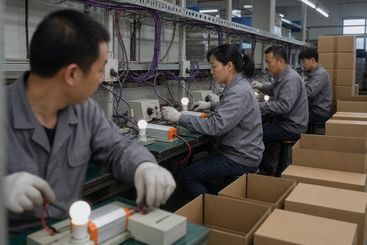












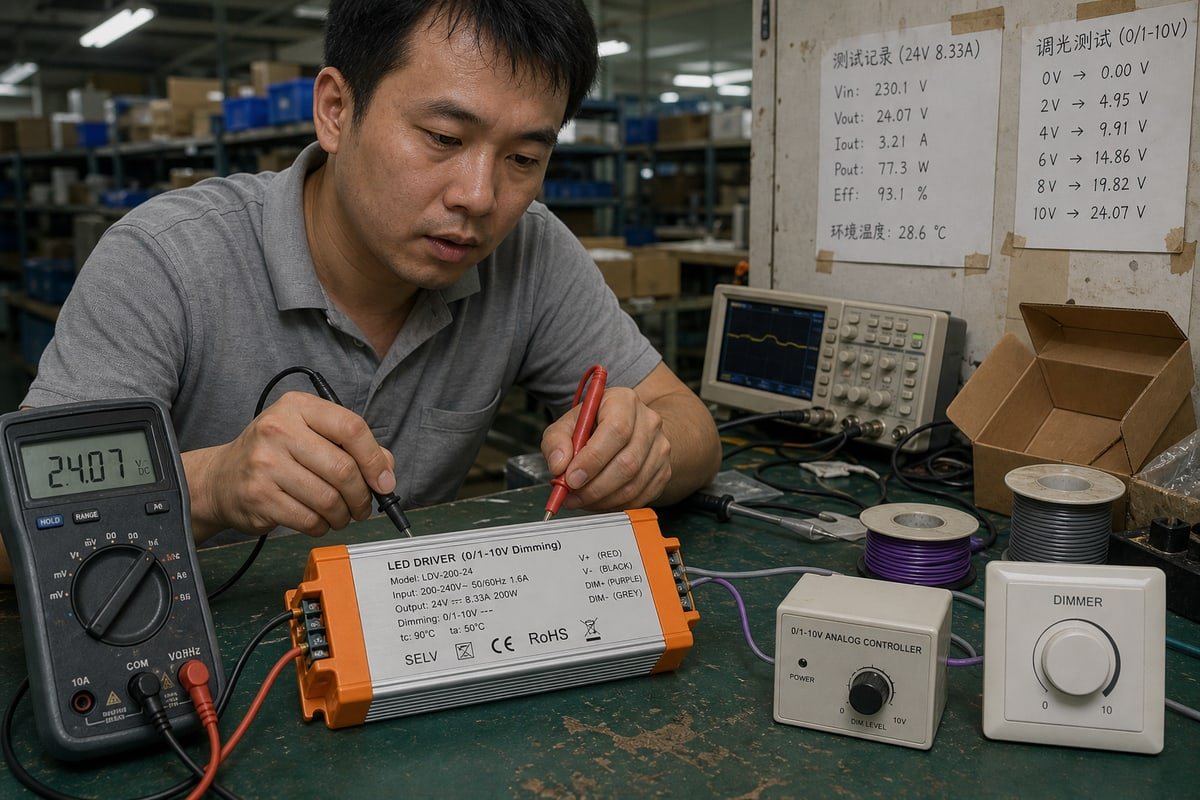
去年,我们的0–10V驱动器在深圳测试台上调光完美,但一位客户的控制器却无法驱动它们。0–10V系统中的电流源与电流灌是罪魁祸首。.
在0–10V调光系统中,电流源配置由控制器生成并向LED驱动器供应控制电流,而电流宿配置则由LED驱动器供应电流,控制器拉低电压;两种设备必须具有互补的源/宿特性。.
最简单的记忆方式:电流源意味着控制器→提供电流→驱动器。电流灌意味着驱动器→提供电流→控制器。这一差异决定了您的灯具是正常调光、行为异常,还是完全无视控制器。下面,我将向您展示如何识别每种类型、选择正确的类型、安全组合它们,并从真正进行测试的供应商处采购。.
在0–10V调光系统中,如何区分电流源和电流阱?
在我们的深圳测试台上,每台驱动器在包装前都通过调光至熄灭检查。这一日常流程让我们的团队能在几秒钟内识别源和灌行为。.
检查哪个设备为控制回路供电。如果控制器自行输出0–10V信号,则为电流源(ANSI E1.3风格)。如果LED驱动器的调光线在未连接时显示10V,则驱动器提供电流,并期望使用灌电流控制器(IEC 60929附录E)。.
混淆源于0–10V看起来像一种通用的模拟信号接口。事实并非如此。同一对紫色和灰色导线可能承载两种截然不同的电气配置,而包装盒上的标签很少告诉您是哪一种。.
跟随电流,而非应用标签
您常会听到一种简化的说法:源是舞台用的,灌是商业用的。我要反驳这种说法。这是一个有用的经验法则,但拓扑结构和标准合规性比应用标签更重要。. ANSI E1.3 1 将舞台调光中的电流源正式化,其中控制器生成电压。. IEC 60929附录E 2 将电流灌正式化,它源于荧光灯灌电流镇流器时代,并直接延续到现代LED驱动器调光。如今,, ANSI C137.1 3 定义了常见的商业配置:LED驱动器通过内部上拉电阻作为电流源,墙壁调光器作为电流灌。根据每个产品的拓扑结构和遵循的标准来判断,而非根据其销售市场。.
| 问题 | 电流源系统 | 电流灌系统 |
|---|---|---|
| 谁生成控制电压? | 控制器 | LED驱动器 |
| 电流方向 | 控制器→驱动器 | 驱动器→控制器 |
| 参考标准 | ANSI E1.3 | IEC 60929附录E、ANSI C137.1 |
| 历史根源 | 舞台调光台 | 荧光灯灌电流镇流器控制 |
| 开路行为 | 取决于驱动器默认状态 | 通常升至全输出 |
快速万用表测试
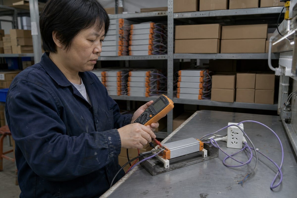
以下是我们日常的做法。断开两线控制电路。测量驱动器DIM+和DIM−引线之间的电压。如果读数接近10V DC,则驱动器提供电流,需要灌电流控制器。如果驱动器的调光引线接近0V,而控制器自行产生电压,则您使用的是源控制器。测量时还要注意信号极性。这是一个 极性DC信号 4, ,知道哪根引线为正极可避免后续麻烦。.
哪种0–10V控制类型,电流源或电流沉,适合我的照明项目?
在两种拓扑之间选择意味着在故障安全行为与现有控制生态系统之间权衡。我们在几乎每个合作开发项目中都会引导OEM客户进行这种权衡。.
对于大多数建筑和商业LED驱动调光,请选择电流吸收方式,因为ANSI C137.1规定驱动器为源,墙壁调光器为吸收端,从而在开路时实现失效安全的满输出。当采用源型控制器、PLC模拟输出或剧场E1.3系统驱动信号时,请选择电流源方式。.

从这张快速地图开始,然后阅读下面的推理。.
| 项目类型 | 典型拓扑 | 适用原因 |
|---|---|---|
| 办公室、零售、仓库 | 灌电流调光器+源驱动器(ANSI C137.1) | 故障安全:切断控制线时灯具默认100%亮度 |
| 剧院和舞台设备 | Sourcing controller (ANSI E1.3) | The desk generates the signal; fixtures interpret it |
| Industrial automation | Sourcing controller via PLC analog output | Most PLCs default to sourcing outputs |
| Building management systems | Verify the I/O design first | Sink capacity on BMS ports is limited and must be checked |
The fail-safe point deserves emphasis. In a compliant sinking system, if someone cuts the control wires, the circuit goes open, the driver's internal voltage rises to 10V, and the lights jump to full output. For an office or a warehouse, lights stuck at full brightness is an annoyance. Lights stuck off is a safety incident. That is why the sinking convention won in commercial buildings.
The industrial case runs the other way. PLCs usually ship with sourcing analog outputs. Connect one directly to a sinking-expectation setup without checking, and you get a compatibility conflict that may need an interface relay or a signal converter to resolve. We have supplied exactly that kind of bridge hardware to engineering firms in Germany and Italy.
有源与无源控制
One more layer matters: Active vs Passive Control on the sink side. A passive sink, like a simple potentiometer 5, creates non-linear dimming curves that shift as you add or remove drivers. An active electronic sink holds a consistent voltage-to-light ratio regardless of load. Our rotary wall dimmers use active sink circuitry for precisely this reason, because a distributor's customer notices when ten fixtures dim differently than the showroom sample did.
我可以在同一个0–10V调光电路中混合使用电流源和电流宿设备吗?
A procurement manager in Singapore once messaged me on WhatsApp: her single sample dimmed beautifully, but the fifty-unit pilot floor would not drop below half brightness. The answer sat in source and sink current math.
You should not mix current source and current sink devices unless one side is designed to handle both. Pair a sourcing driver with a sinking controller, or a sourcing controller with a sinking driver, and always verify the controller's total sink capacity covers every paralleled driver's source current.

The dangerous assumption in this business is simple: if both products say 0–10V, they are compatible. They are not necessarily. A 0–10V label tells you the control-voltage interface. It does not tell you the topology, the source/sink current, the polarity behavior, or the exact standard implementation. Two mismatched devices can sit on the same two wires and simply talk past each other, producing wrong dimming ranges or no response at all.
计算灌电流
In a sinking network, every driver added in parallel contributes its own source current to the loop. The controller must dissipate the sum of all those currents to pull the line down to 0V. So do not just count drivers. Calculate:
Total sink current ≈ number of drivers × driver source current
Then compare that number with the controller's specified sinking capability, measured in mA. Here is a worked example with illustrative figures:
| Drivers on the Loop | Total Source Current (at 1 mA each, example) | Controller Rated to Sink 5 mA | Controller Rated to Sink 30 mA |
|---|---|---|---|
| 1 | 1 mA | Works | Works |
| 5 | 5 mA | Marginal, curve distorts | Works |
| 10 | 10 mA | Cannot reach minimum level | Works |
This is exactly what happened in that Singapore pilot: one driver dimmed perfectly, but ten drivers exceeded the controller's sink capacity, so the line could never be pulled low enough.
需要注意的接线细节
Beyond the math, watch four things. First, signal polarity: 0–10V is a polarized DC signal, and reversing DIM+ and DIM− will prevent dimming or can damage the controller. Second, voltage drop on long control runs, which quietly compresses your dimming range. Third, grounding: a floating common in sinking drivers can cause flickering when the control signal ground drifts from the driver's internal reference. Fourth, modern wireless 0–10V controllers often harvest their operating power from the driver's source current, so they only function with genuinely sourcing drivers.
Before you connect anything, run this checklist:
- Identify the topology: source or sink?
- Check source current: how many mA does each driver provide?
- Check sink capacity: how many mA can the controller absorb?
- Check polarity: verify DIM+ and DIM−.
- Check the standard: do not assume every 0–10V interface behaves identically.
- Check minimum output: confirm what the driver actually does at 0V, not what the datasheet calls 0%.
- Test the complete combination: controller, the real number of drivers, and the real LED load.
如何为电流源或电流沉0–10V系统选择可靠的LED驱动电源供应商?
Two decades around this industry taught me one hard lesson: buyers rarely regret asking tough technical questions, but they often regret assuming the datasheet told the whole story.
选择公布源电流和灌电流额定值、明确每个0–10V接口遵循的标准、以实际数量测试控制器加驱动器组合,并提供OEM/ODM工程支持的供应商。可靠的合作伙伴会在发货前验证完整的调光范围,而不仅仅是数据表上的0–10V标签。.
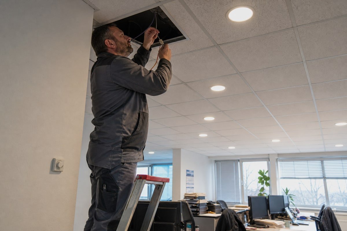
The real compatibility question is never "are both products 0–10V?" It is "can this controller electrically drive this exact number of these drivers across the entire required dimming range?" A supplier who cannot answer that question about their own products will leave you answering it during commissioning, at your cost and on your deadline.
Here is the evaluation framework I encourage our distributor and private-label clients to use, because it is the same one we hold ourselves to:
| What to Ask | Green Flag | Red Flag |
|---|---|---|
| Which standard does the interface follow? | Names IEC 60929 Annex E, ANSI C137.1, or E1.3 explicitly | Says only "standard 0–10V" |
| What is the source/sink current spec? | Publishes mA figures for both roles | Voltage range only |
| Can you test my exact combination? | Bench-tests controller + quantity + load | "It should work" |
| What happens at 0V? | States real minimum output behavior | Repeats "0%" without context |
| Certifications and markings? | CE, CB, SAA, SELV visible on the label | Vague or missing marks |
| Customization support? | OEM/ODM development, logo printing, terminal labeling | Catalog-only sales |
On our own line, every driver ships in an aluminum housing with heat-dissipation fins and clearly printed L, N, LED, and 0–10V terminals, because ambiguous wiring labels cause a surprising share of field polarity mistakes. Before a batch leaves for Singapore, Japan, Germany, or Australia, we run the client's specified controller against the actual driver quantity and LED load, across the whole dimming range. When a client in France needed a sinking dimmer matched to third-party sourcing drivers, our engineers requested the drivers' source current spec first and sized the sink stage around it. That is the level of detail worth demanding from any partner, including us. It protects your project cost, your deadline, and your brand's name on the box.
结论
Current source vs current sink in 0–10V systems is a compatibility question, not a label. Match topologies, verify sink capacity, and test complete combinations before any driver ships.
脚注
1. The ESTA Technical Standards Program maintains the ANSI E1.3 standard for theatrical 0-10V control. ↩︎
2. The International Electrotechnical Commission webstore provides the official IEC 60929 standard for lighting control. ↩︎
3. Official site of NEMA, the body responsible for the ANSI C137.1 lighting interface standard. ↩︎
4. Explains the nature of direct current signals where polarity is a critical factor. ↩︎
5. Technical definition of a potentiometer, used as a passive sink in analog dimming circuits. ↩︎