















Les bandes LED TRIAC qui refusent de s'éteindre complètement ont failli nous coûter une relation avec un distributeur majeur en Allemagne l'année dernière — et cette plainte a enseigné une leçon critique à notre équipe d'ingénierie.
Les bandes LED TRIAC ne s'éteignent pas complètement car un petit courant de fuite circule à travers le variateur même à l'état éteint. Cette tension résiduelle alimente partiellement le driver LED dimmable, et comme les LED nécessitent très peu de puissance pour émettre de la lumière, la bande produit une lueur faible ou un flash périodique.
La cause profonde n'est presque jamais la bande LED elle-même. C'est l'interaction entre le variateur, le Pilote de LED 1, et la charge connectée. Ci-dessous, je détaille exactement pourquoi cela se produit et ce que vous pouvez faire à ce sujet.
Qu'est-ce qui fait que mes bandes LED TRIAC restent faiblement éclairées même après les avoir éteintes ?
Lors d'un audit d'usine le trimestre dernier, nous avons connecté la même bande LED à trois variateurs TRIAC différents sur notre banc de test — et obtenu trois résultats complètement différents à l'état éteint.
La cause principale est le courant de fuite du variateur. Les semi-conducteurs TRIAC n'atteignent jamais un circuit ouvert parfait, donc 1 à 5 mA de courant peuvent passer même lorsque le variateur est éteint. Ce minuscule courant est invisible pour les ampoules à incandescence mais suffisant pour faire luire les bandes LED.

Pourquoi les LED réagissent aux micro-courants
Les ampoules incandescentes nécessitent un courant substantiel pour chauffer un filament. Les LED non. Un courant qui serait complètement invisible dans une lampe halogène de 60 W peut produire un effet de ghosting notable dans une bande LED nominale de seulement quelques watts. Ce n'est pas un défaut. C'est une conséquence directe de l'efficacité des LED. La jonction semi-conductrice 2 à l'intérieur de chaque LED peut émettre des photons à des niveaux de micro-ampères. Cette sensibilité est ce qui rend les LED économes en énergie — et aussi ce qui les rend vulnérables à chaque milliampère parasite dans le circuit.
Les cinq causes profondes
J'ai classé les causes par fréquence de rencontre dans les retours terrain réels :
| Cause | Ce qui se passe | Fréquence |
|---|---|---|
| Variateur courant de fuite 3 | 1–5 mA passe à travers le TRIAC même éteint | Très courant |
| Exigence de charge minimale non respectée | Le variateur ne peut pas fonctionner correctement en dessous de sa charge LED nominale | Courant |
| Couplage capacitif dans le câblage | Les fils sous tension adjacents induisent une tension fantôme dans le fil commuté | Modéré |
| Énergie stockée dans les condensateurs du driver | Les condensateurs électrolytiques se déchargent lentement à travers les LED | Modéré |
| Seuil de tension minimal du firmware du variateur | Les variateurs numériques fixent une sortie minimale au-dessus du vrai zéro volt | Moins courant |
Il y a aussi un courant de maintien 4 problème qui mérite d'être compris. Un TRIAC reste verrouillé — conducteur — jusqu'à ce que le courant qui le traverse descende en dessous d'un seuil appelé courant de maintien à chaque passage par zéro du secteur. Avec de très petites charges LED, le courant peut osciller près de ce seuil. Le TRIAC peut ne pas se réinitialiser complètement à son état non conducteur à chaque cycle. Le résultat est imprévisible : parfois la bande s'éteint, parfois non.
Comportement en leading edge vs trailing edge
Un variateur leading edge coupe l'avant de chaque demi-cycle AC. Un variateur trailing edge coupe l'arrière. Les deux types de gradation par coupure de phase 5 peuvent fuir du courant, mais ils se comportent différemment en bas de la plage de variation.
Lors de nos tests, les variateurs à coupure de phase descendante produisent généralement un gradation plus fluide en bas de plage. Mais “ plus fluide ” ne signifie pas toujours “ zéro réel ”. Les deux types peuvent laisser une tension résiduelle atteindre le driver si le réseau snubber interne du variateur crée un chemin de dérivation. Ce snubber — un circuit RC conçu pour protéger le TRIAC contre les pics de tension — est un chemin AC permanent entre la ligne et la charge. Il existe dans presque tous les dispositifs de gradation à coupure de phase.
Le cycle de charge qui provoque le clignotement
Parfois la bande ne brille pas continuellement. Au lieu de cela, elle clignote toutes les quelques secondes. Cela se produit parce que le courant de fuite charge lentement les condensateurs d'entrée à l'intérieur du driver LED. Quand suffisamment d'énergie s'accumule, le driver démarre brièvement, délivre une impulsion de puissance aux LED, et les condensateurs se déchargent. Puis le cycle se répète :
Courant de fuite → le condensateur se charge → le driver démarre brièvement → les LED clignotent → le condensateur se décharge → le cycle se répète
Ce clignotement périodique est plus alarmant pour les utilisateurs finaux qu'une faible lueur, mais la cause profonde est la même : un courant résiduel du variateur atteignant un driver qui a besoin de très peu d'énergie pour se réveiller.
Comment puis-je résoudre le problème de lueur résiduelle lors de l'utilisation de variateurs TRIAC avec des bandes LED ?
Le compromis que nous évaluons sur chaque projet est simple : faut-il traiter le symptôme du côté de la charge, ou résoudre le problème au niveau du variateur-pilote ?
Vous pouvez corriger la lueur résiduelle en ajoutant une résistance de charge fictive ou un condensateur de dérivation LED aux bornes de la sortie, en remplaçant le variateur par un modèle conçu pour les faibles charges LED, ou — de manière plus fiable — en utilisant un ensemble variateur et driver LED dimmable assortis, testés ensemble comme un système complet.

Solutions rapides vs solutions appropriées
Chaque solution ne présente pas le même risque ni le même coût. Voici une comparaison classée du plus simple au plus fiable :
| Correctif | Comment ça fonctionne | Pour | Cons |
|---|---|---|---|
| Résistance de charge fictive | Ajoute une charge résistive pour élever la puissance totale au-dessus de l'exigence de charge minimale du variateur | Économique, rapide à installer | Gaspille de l'énergie, peut surchauffer si mal dimensionnée |
| Condensateur de dérivation LED | Absorbe le courant de fuite et l'empêche d'atteindre le pilote | Petit, peu coûteux | Doit être correctement dimensionné ; une valeur incorrecte peut provoquer un scintillement ou un risque de sécurité |
| Remplacer le variateur | Utiliser un variateur avec une charge minimale plus faible et une certification LED appropriée | Résout la cause racine au niveau de l'interrupteur | Coût plus élevé, nécessite un recâblage |
| Système variateur-pilote apparié | Utiliser un pilote et un variateur testés ensemble pour une compatibilité sur toute la plage | Meilleure fiabilité dans toutes les conditions de variation | Nécessite un approvisionnement auprès d'un seul écosystème testé |
| Déconnexion physique à base de relais | Un relais ouvre physiquement le circuit lorsque le variateur atteint zéro | Véritable isolation galvanique, courant nul garanti | Ajoute de la complexité, du coût et un composant supplémentaire |
Pourquoi les composants aléatoires sont dangereux
L'une des plus grandes erreurs que je vois sur le terrain est un installateur ajoutant une résistance ou un condensateur aléatoire pour éliminer l'effet de lueur résiduelle. Si le composant est sous-dimensionné, il surchauffe. S'il est surdimensionné, il interfère avec les performances de variation. Et s'il n'est pas certifié pour la tension secteur, il devient un risque d'incendie.
Notre équipe d'ingénierie a testé des dizaines de composants “ correctifs ” du marché secondaire. Les résultats sont incohérents. Certains fonctionnent avec un variateur et échouent avec un autre. Certains fonctionnent à température ambiante mais échouent lorsque le boîtier du driver chauffe pendant le fonctionnement estival. La dérive thermique de la sensibilité de gâchette du TRIAC aggrave le courant de fuite à mesure que les températures augmentent, de sorte qu'un correctif qui fonctionne dans un laboratoire frais peut échouer dans un plénum de plafond à 45 °C.
Je déconseille fortement l'ajout de composants non spécifiés sans consulter le fabricant du pilote. Le correctif le moins cher n'est pas toujours le plus sûr.
L'approche au niveau système
La voie la plus fiable consiste à traiter le variateur, le pilote et la charge LED comme un seul système intégré. Lorsque nous développons nos pilotes LED TRIAC à tension constante Boqi, nous les testons contre une liste de modèles de variateurs à coupure de phase descendante et à coupure de phase montante compatibles. Ces tests de compatibilité couvrent le comportement au démarrage, la plage de variation, le scintillement et — surtout — le comportement à l'extinction.
Un système correctement apparié élimine entièrement le besoin de composants de dérivation. Il améliore également la stabilité de la variation, les performances en bas de plage et la fiabilité au démarrage. C'est pourquoi nous recommandons toujours à nos distributeurs et fabricants d'éclairage de spécifier le variateur et le pilote ensemble, et non comme des postes séparés.
La même bande LED peut s'éteindre parfaitement avec le variateur A, luire faiblement avec le variateur B et scintiller avec le variateur C. Les variateurs TRIAC ne sont pas électriquement identiques, même lorsqu'ils sont tous commercialisés comme “ compatibles LED ”. C'est le problème fondamental, et l'appariement au niveau du système est la solution fondamentale.
Quels drivers LED dois-je spécifier pour éviter une extinction incomplète dans mes projets de gradation TRIAC ?
Une responsable des achats à Singapour m'a un jour raconté qu'elle avait testé quatre drivers “ compatibles TRIAC ” différents de quatre fournisseurs — et qu'un seul s'éteignait proprement avec le variateur de son projet.
Spécifiez un driver LED dimmable qui répertorie un tableau de compatibilité de variateurs testés, prend en charge la gradation par coupure de phase en front montant et en front descendant, présente une faible consommation en veille et répond à l'exigence de charge minimale du variateur que vous avez choisi. Les drivers sans données de compatibilité publiées sont un pari risqué.

Ce qu'il faut rechercher sur une fiche technique de driver
Toutes les fiches techniques ne vous disent pas ce que vous devez savoir. Voici les spécifications qui comptent le plus pour prévenir une extinction incomplète :
| spécification | Pourquoi c'est important | Ce qu'il faut rechercher |
|---|---|---|
| Type de variation | Confirme la compatibilité avec la variation par coupure de phase | “ TRIAC / coupure de phase montante / coupure de phase descendante ” clairement indiqué |
| Niveau de gradation minimal | Indique jusqu'où le pilote peut varier | 1 % ou moins est idéal ; 5 % ou plus peut ne pas atteindre une véritable extinction avec certains variateurs |
| Puissance en veille | Énergie consommée lorsque le variateur est au minimum | En dessous de 0,5 W réduit la tension résiduelle et le risque de lueur résiduelle |
| Liste des variateurs testés | Prouve la compatibilité dans le monde réel | Modèles de variateurs nommés avec résultats de performance confirmés |
| Plage de tension de sortie | Doit correspondre à votre bande LED | Tension constante : 12 V ou 24 V DC |
| Puissance nominale vs. charge minimale du variateur | Le driver doit tirer suffisamment de courant pour que le variateur fonctionne | Vérifiez que la puissance d'entrée du driver dépasse la charge LED minimale indiquée du variateur |
Tension constante vs courant constant
Pour les applications de ruban LED, vous avez presque toujours besoin d'un driver à tension constante. Le ruban lui-même contient des résistances intégrées qui régulent le courant vers chaque grappe de LED. Un driver à courant constant est conçu pour différents types de luminaires — panneaux lumineux, downlights et produits similaires où les LED sont câblées en série.
Lorsque nous concevons nos drivers LED TRIAC à tension constante Boqi, l'étage d'entrée est optimisé pour les signaux de gradation par coupure de phase. Cela signifie que le étages de correction du facteur de puissance 6 circuit et le filtre EMI sont accordés pour que les condensateurs Y du filtre ne créent pas de chemins de fuite excessifs. La fuite des condensateurs Y du filtre EMI est l'une des causes les moins évidentes de lueur fantôme. Le filtre lui-même peut laisser fuir de minuscules courants vers la masse du châssis, et si le ruban LED est monté sur un profilé en aluminium mis à la terre, un circuit fantôme se forme qui contourne entièrement le chemin d'alimentation prévu.
Pourquoi “ Compatible LED ” ne suffit pas
De nombreux variateurs sont commercialisés comme “ compatibles LED ”, mais ce label n'a aucune norme universelle derrière lui. Il signifie simplement que le variateur a été conçu en tenant compte des charges LED. Il ne garantit pas un fonctionnement propre avec votre driver spécifique.
Il en va de même du côté du driver. Un driver étiqueté “ dimmable TRIAC ” confirme qu'il peut accepter une entrée AC à coupure de phase. Il ne confirme pas une gradation fluide, un démarrage fiable ou une extinction complète avec tous les variateurs TRIAC du marché.
C'est exactement pourquoi nous publions des listes de compatibilité de variateurs testés avec nos drivers Boqi. Notre équipe à Shenzhen fait passer chaque modèle de driver par une batterie de variateurs des marchés vers lesquels nous exportons — y compris des modèles courants au Royaume-Uni, en Allemagne, en Australie et en Asie du Sud-Est. Ce processus prend du temps, mais il évite à nos distributeurs des défaillances coûteuses sur le terrain et des réclamations au titre de la garantie.
La vraie question qu'un responsable des achats devrait poser n'est pas “ Ce driver est-il dimmable TRIAC ? ” mais “ Ce driver a-t-il été testé avec le variateur spécifique utilisé par mon projet ? ” Si le fournisseur ne peut pas répondre à cette question avec des données, le risque vous incombe.
Comment puis-je tester la compatibilité TRIAC avant de confirmer une commande en gros avec mon fournisseur ?
Une leçon que nous avons apprise au début de notre activité d'exportation : ne jamais approuver une commande en gros sur la base d'un seul test de banc à température ambiante avec des fils courts.
Testez la compatibilité TRIAC en faisant fonctionner le driver LED et le variateur ensemble selon un protocole structuré qui vérifie le démarrage, la gradation sur toute la plage, la stabilité en bas de plage, le scintillement et l'extinction complète — puis répétez à température élevée et avec une longueur de câble maximale pour simuler les conditions réelles du terrain.
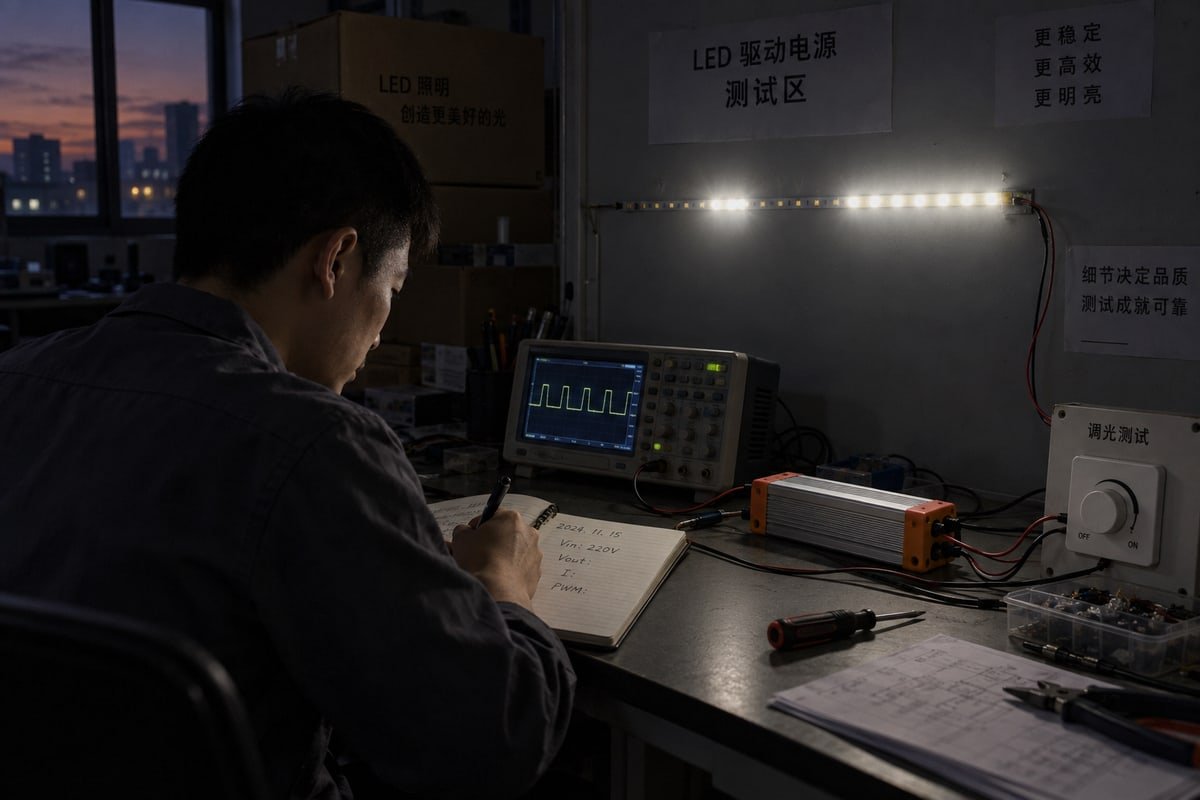
Un protocole de test pratique en sept étapes
Voici le protocole que nous utilisons en interne avant d'approuver un appariement variateur-driver pour une expédition de production :
- Test de démarrage à froid. Mettez le variateur sous tension à partir de zéro. Le ruban LED doit s'allumer progressivement sans s'allumer brusquement à un niveau de luminosité aléatoire.
- Balayage sur toute la plage. Graduez lentement de 100 % au minimum. Surveillez les scintillements, les paliers ou les sauts de luminosité brusques.
- Maintien en bas de plage. Réglez le variateur à son niveau visible le plus bas et laissez-le pendant 10 minutes. La sortie doit rester stable sans scintillement visible.
- Test d'extinction. Éteignez le variateur. Le ruban doit s'éteindre complètement en 2 secondes, sans lueur résiduelle ni clignotement périodique.
- Test thermique. Enfermez le driver dans un espace qui simule un vide de plafond ou une cavité de meuble. Faites-le fonctionner pendant 2 heures à faible niveau de gradation, puis répétez le test d'extinction. La dérive thermique de la sensibilité de gâchette du TRIAC augmente le courant de fuite lorsque l'appareil est chaud.
- Test de longueur de câble. Ajoutez la longueur de câble maximale que vous prévoyez dans l'installation réelle. Des fils plus longs augmentent le couplage capacitif, ce qui peut introduire une tension fantôme dans le circuit LED.
- Test multi-unités. Connectez le nombre de drivers que vous prévoyez d'installer sur un seul circuit de variateur. Plusieurs drivers modifient la charge totale et peuvent pousser le système en dehors de la fenêtre de fonctionnement du variateur.
À quoi ressemblent les défaillances
Chaque schéma de défaillance correspond à une cause racine différente. Utilisez ce tableau pour diagnostiquer ce que vous observez pendant les tests :
| Symptôme pendant le test | Cause probable | Action recommandée |
|---|---|---|
| Le ruban s'allume à 30 % au lieu de 0 % | Seuil de tension minimal du firmware du variateur réglé trop haut | Essayez un autre variateur ou demandez un ajustement du firmware |
| Le ruban scintille à bas niveaux | Le signal de coupure de phase est instable à faible angle de conduction | Passez d'un variateur à front montant à un variateur à front descendant |
| Faible lueur lorsqu'éteint | Courant de fuite ou contournement du réseau snubber | Confirmez la compatibilité variateur-driver ou utilisez un système apparié |
| Clignotement périodique toutes les 3 à 5 secondes | Cycle de charge-décharge du condensateur dû à la tension résiduelle | Ajoutez un condensateur de dérivation LED testé ou passez à un variateur compatible |
| Fonctionne à température ambiante mais lueur lorsqu'il est chaud | La dérive thermique augmente le courant de fuite du TRIAC | Utilisez un variateur avec une spécification de fuite plus faible |
Combien d'échantillons tester
Je recommande de tester au moins 3 échantillons de chaque composant. Les tolérances de fabrication font qu'un échantillon peut passer tandis qu'un autre échoue à la marge. Si 1 échantillon sur 3 échoue au test d'extinction, c'est un signal d'alarme pour la fiabilité sur le terrain. Nous appliquons cette règle à notre propre production — chaque lot de drivers LED TRIAC Boqi passe par des contrôles ponctuels de compatibilité avec les variateurs avant que nous approuvions l'expédition.
Quand demander des échantillons avant de commander
Si votre fournisseur ne peut pas fournir une liste de compatibilité de variateurs testés, demandez des échantillons et exécutez le protocole ci-dessus vous-même. Le coût de 5 drivers échantillons et d'une semaine de tests est bien inférieur au coût d'un rappel sur le terrain de milliers d'unités. C'est le conseil que je donne à chaque nouveau distributeur qui nous contacte via notre site web ou lors de salons professionnels.
Un système de gradation TRIAC doit toujours être évalué comme un système complet. La question importante n'est pas “ Est-ce un variateur TRIAC ? ” La question est “ Ce variateur a-t-il été testé et prouvé compatible avec ce driver LED spécifique ? ” L'utilisation d'une combinaison testée — telle que les drivers LED TRIAC à tension constante Boqi associés aux variateurs Boqi à coupure de phase montante et descendante compatibles — offre aux installateurs et aux fabricants d'éclairage des performances plus prévisibles en matière de démarrage, de plage de gradation, de contrôle du scintillement et de comportement d'extinction.
C'est la vraie différence entre un système qui gradate avec succès lors d'un test rapide sur banc et un qui fonctionne de manière fiable dans une installation réelle pendant des années.
Conclusion
Les bandes LED TRIAC qui ne s'éteignent pas sont un problème système, pas un défaut de la bande. Appariez votre variateur, votre driver LED dimmable et votre charge comme un système testé pour éliminer définitivement la lueur résiduelle.

Vous souhaitez vous approvisionner en produits mentionnés dans cet article ? Consultez les détails et demandez un devis ici :
Notes de bas de page
Fournit un aperçu technique des drivers LED et de leur rôle fondamental dans les circuits d'éclairage. ↩︎
Explication faisant autorité sur le fonctionnement des jonctions semi-conductrices LED et leur efficacité énergétique inhérente. ↩︎
Définition scientifique et contexte d'ingénierie du courant de fuite dans les circuits électroniques et les semi-conducteurs. ↩︎
Explique le fonctionnement du semi-conducteur TRIAC et le concept de courant de maintien référencé dans l'article. ↩︎
Normes industrielles pour la compatibilité de gradation entre l'éclairage à semi-conducteurs et les systèmes de gradation à coupure de phase. ↩︎
Explique le concept électrique de correction du facteur de puissance utilisé dans les systèmes d'éclairage à haut rendement. ↩︎