















Elegir entre leading-edge y trailing-edge para drivers de CC descarriló el lanzamiento de uno de nuestros clientes el año pasado. Si eliges mal, las quejas por parpadeo se multiplican. Nuestro laboratorio en Shenzhen ve esto semanalmente.
El dimming leading-edge corta el inicio de cada medio ciclo de CA, mientras que el trailing-edge corta el final. Un driver de corriente constante compatible con corte de fase detecta la forma de onda restante y regula la corriente del LED en consecuencia. Ningún método es universalmente mejor: el driver debe soportar específicamente el método de dimming seleccionado en todo el rango de carga y atenuación requerido.
Esa respuesta breve oculta muchos detalles de ingeniería. A continuación, desglosaré cómo funciona cada método, cuál se adapta a tu línea de productos, cómo evitar fallos de compatibilidad y cómo funciona el desarrollo personalizado para marcas de etiqueta privada.
¿Cómo difieren realmente el dimming leading-edge y trailing-edge para drivers de CC?
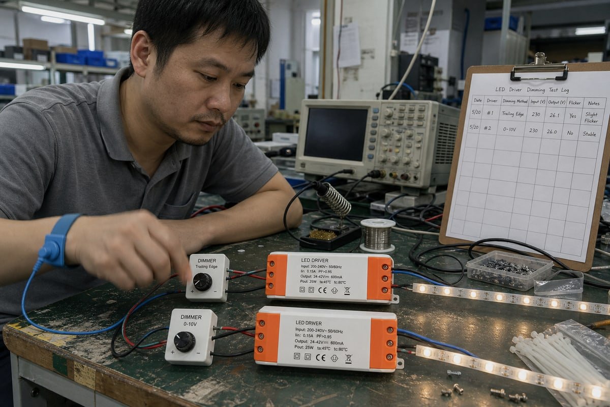
Durante una reciente ejecución de control de calidad en nuestra fábrica, dos dimmers de apariencia idéntica produjeron un comportamiento de extremo bajo completamente diferente en el mismo driver. La diferencia se reducía a qué parte de la forma de onda se cortaba.
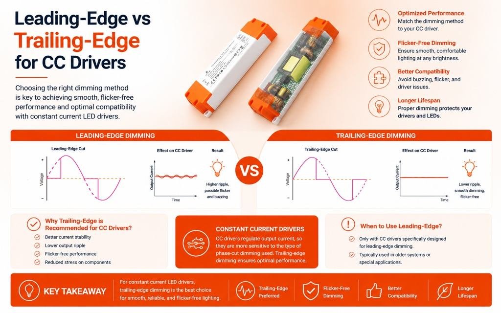
Para un driver de corriente constante atenuable por corte de fase, el dimming leading-edge elimina el inicio de cada medio ciclo de CA usando un TRIAC, mientras que el trailing-edge elimina el final usando un MOSFET. El driver lee el ángulo de conducción restante y establece la corriente del LED según su propio algoritmo de control.
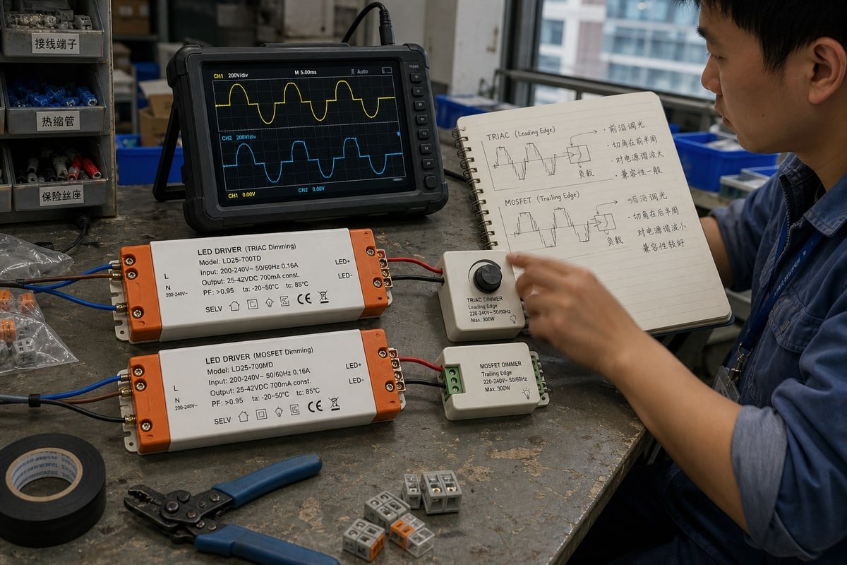
La tecnología de corte de fase no es un término de marketing. Describe exactamente cómo se corta la onda senoidal de CA antes de llegar al driver. Aquí está la comparación clave de un vistazo:
| Rasgo | Borde de ataque | Borde de caída |
|---|---|---|
| Otro nombre | Fase directa | Fase inversa |
| Corte de forma de onda | Inicio de cada semiciclo | Fin de cada semiciclo |
| Interruptor común | TRIAC | MOSFET/interruptor electrónico |
| Cargas históricas típicas | Incandescente, halógeno, magnético (cargas inductivas) | Drivers electrónicos, cargas capacitivas |
| Compatibilidad con LED de CC | Debe especificarse | Debe especificarse |
| Preocupación típica | Inrush, ruido acústico, carga mínima | Compatibilidad del driver, comportamiento de control |
Qué sucede dentro de la forma de onda
Los dimmers leading-edge usan Regulación de intensidad con TRIAC, una forma de control de fase directa. Esperan después del cruce por cero y luego se encienden abruptamente. Ese borde duro crea picos de voltaje y una corriente de inrush pronunciada. Los dimmers trailing-edge usan dimming de fase inversa a través de un MOSFET. Conducen desde el inicio del medio ciclo y se apagan suavemente antes del final. La transición es más suave, por lo que la EMI y el zumbido audible suelen ser menores.
Por qué el driver, no el dimmer, establece la corriente
Aquí está el punto que la mayoría de los artículos omiten. La forma de onda con corte de fase nunca se entrega directamente a los LEDs. La cadena real es: CA de red → dimmer con corte de fase → etapa de entrada del driver de CC → circuito de control → corriente LED regulada → LEDs. El driver mide la ángulo de conducción 1 y la traduce en un comando de corriente. Entonces, un ángulo de fase del 40% no significa automáticamente una corriente LED del 40%. El algoritmo de control del driver decide esa asignación. En nuestros propios diseños, moldeamos esa curva deliberadamente para que el brillo se sienta suave al ojo humano.
¿Qué tipo de dimming debo elegir para mi línea de productos LED?
Cada semana sopeso la misma compensación con los compradores: trailing-edge ofrece un rendimiento más suave en drivers modernos, pero leading-edge protege los presupuestos cuando un proyecto debe reutilizar infraestructura TRIAC instalada.
Elige el tipo de dimming que soporta la especificación de tu driver, no una regla general. Trailing-edge se adapta a la mayoría de los drivers de CC electrónicos modernos y circuitos de baja potencia; leading-edge se adapta a ecosistemas TRIAC heredados y retrofits. Verifica la carga mínima, la corriente de atenuación mínima y el rango de ángulo de conducción antes de comprometerte con cualquiera de los métodos.

Déjame ser directo sobre un mito técnico común. Trailing-edge no es inherentemente mejor solo porque su transición de conmutación es más suave. En la práctica, la arquitectura de entrada del driver, la compatibilidad del dimmer, el requisito de carga mínima y la estrategia de control importan más que el método de corte de fase por sí solo. He visto sistemas donde un dimmer trailing-edge supuestamente mejor funcionó peor que uno leading-edge, porque el circuito de entrada del driver de CC estaba específicamente optimizado para operación TRIAC de fase directa.
El proceso de selección correcto es el siguiente:
- Revisa primero la especificación del driver.
- Confirma el tipo de corte de fase soportado.
- Verifica la compatibilidad del dimmer desde la lista probada.
- Iguala la carga mínima y máxima.
- Confirme que el rango de atenuación requerido está garantizado.
No: LED = borde de caída.
Dónde suele ganar cada método
| Escenario | Mejor ajuste | Por qué |
|---|---|---|
| Readaptación con atenuadores TRIAC instalados | Borde de ataque | Reutiliza los controles existentes; la opción más económica cuando el driver está certificado para fase directa |
| Circuitos de baja potencia por debajo de 25 W | Borde de caída | Los atenuadores de borde de subida a menudo requieren una carga mínima de 25 W–40 W, lo que causa parpadeo o estroboscopía por debajo de ese nivel |
| Proyectos de atenuación profunda | Borde de caída | Puede alcanzar alrededor del 1% de forma estable; los diseños basados en GaN reducen por debajo del 0,1% |
| Líneas residenciales económicas | Borde de ataque | Los atenuadores son más baratos y están ampliamente disponibles |
| Hostelería o comercio minorista premium | Borde de caída | Curva más suave, menor ruido, rendimiento sin parpadeo en niveles bajos |
La trampa del extremo bajo
La mayoría de las fallas aparecen por debajo del 10–20% de brillo. Un sistema puede verse perfecto desde el 100% hasta el 50%, y luego desarrollar parpadeo, caídas, destellos o una zona muerta a medida que el ángulo de conducción se reduce. Recuerde que la carga mínima del LED y la corriente mínima de atenuación son dos especificaciones diferentes. Un driver puede operar una carga de 350 mA perfectamente a plena salida y, sin embargo, perder regulación cerca de su límite inferior. También hay un ángulo de vida útil: los picos duros de dV/dt de la operación de borde de subida estresan los capacitores electrolíticos de entrada del driver, y algunos datos de la industria sugieren que esto puede acortar la vida útil del driver hasta en un 30% en comparación con la operación de borde de caída. Eso importa cuando su marca asume la garantía.
¿Los drivers de CC trailing-edge causarán problemas de compatibilidad con interruptores dimmer existentes?
Un gerente de compras en Singapur me escribió una vez por WhatsApp con una foto de luces fantasma en un pasillo de hotel terminado. El culpable era un atenuador incompatible, no un driver defectuoso.
Los drivers CC de borde de caída pueden causar problemas en circuitos de atenuadores TRIAC heredados, pero los problemas son evitables. Los drivers universales de corte de fase con detección automática aceptan tanto el control de fase directa como el inverso. Siempre pruebe el par exacto de driver-atenuador, verifique el requisito de carga mínima y siga la lista de compatibilidad del fabricante.
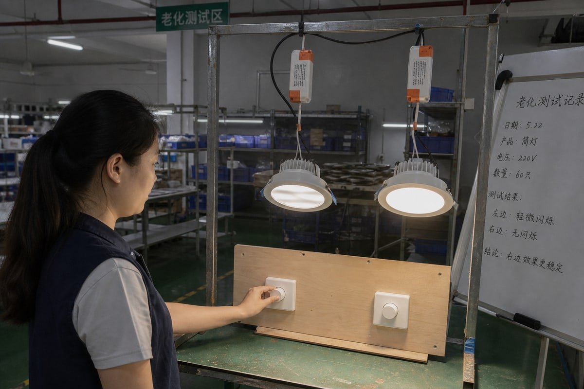
La compatibilidad es donde los proyectos prosperan o fracasan, y una etiqueta de “atenuable” en la caja nunca es suficiente. Diferentes síntomas apuntan a diferentes desajustes, por lo que siempre comienzo la resolución de problemas desde esta tabla:
| Síntoma | Causa probable | Solución práctica |
|---|---|---|
| Parpadeo en niveles bajos | Ángulo de conducción por debajo del mínimo del driver | Aumente el ajuste de extremo bajo del atenuador o elija un driver con menor corriente mínima de atenuación |
| Zumbido audible | Conmutación TRIAC dura que excita los componentes del driver | Cambie a atenuación de fase inversa o a un driver amortiguado para fase directa |
| Luces fantasma cuando está apagado | Corriente de fuga a través del atenuador | Use un driver con amortiguación adaptativa o control de sangrado |
| Sobrecalentamiento o falla del atenuador | Corriente de irrupción acumulada de múltiples drivers | Reduzca la capacidad del atenuador o use borde de caída con comportamiento de arranque suave |
| Zona muerta en el dial | Curva del driver desajustada con el rango del atenuador | Recalibre la curva de atenuación a nivel del driver |
Los circuitos con múltiples drivers requieren cuidado especial
Cuando varios drivers CC cuelgan de un solo atenuador de borde de subida, cada evento de disparo TRIAC 2 desencadena una corriente de irrupción simultánea de todas las cargas capacitivas a la vez. En casos severos, esa sobretensión acumulada puede soldar los contactos del atenuador. Los MOSFET de borde de caída mitigan esto mediante sus características inherentes de arranque suave, y un circuito de arranque suave bien diseñado dentro del driver ayuda aún más. Por eso siempre preguntamos a los compradores cuántos drivers comparten un atenuador antes de cotizar una solución.
Los drivers universales reducen la brecha
Los drivers CC universales más nuevos usan procesamiento de señal digital 3 para auto-detectar el método de corte de fase y reconfigurar la amortiguación interna en tiempo real, lo que también ayuda a eliminar las luces fantasma. Reducen el riesgo, pero no son magia. La carga mínima, la calidad del atenuador y las condiciones del cableado aún deciden el resultado, por lo que probamos en banco cada driver atenuable ELV contra los modelos reales de atenuador del comprador antes del envío. A veces, la respuesta de readaptación más económica es simplemente mantener el atenuador de borde de subida existente y especificar un driver certificado para él.
¿Puedo obtener drivers de CC personalizados leading-edge o trailing-edge para mi marca de etiqueta privada?
Al principio de nuestro negocio de exportación, aprendimos una lección difícil: enviar un driver estándar a un mercado con un ecosistema de atenuadores desconocido crea devoluciones. El desarrollo personalizado resuelve eso de antemano.
Sí. Los proveedores OEM/ODM pueden construir drivers CC de borde de subida, borde de caída o universales de corte de fase según su especificación, incluida la corriente de salida personalizada, la curva de atenuación, el nivel mínimo de atenuación, la carcasa, la impresión del logotipo y certificaciones como CE, CB, SAA y SELV. Espere muestreo, pruebas de compatibilidad con atenuadores y validación de control de calidad antes de la producción en masa.

Nuestros propios drivers compactos—las unidades blancas y naranjas con terminales de tornillo y marcas impresas CE, CB, SAA y SELV 4—comenzaron como proyectos ODM para propietarios de marcas en Europa, el Sudeste Asiático y Australia. La carcasa, el diseño de la etiqueta e incluso la curva de atenuación se moldearon en torno al mercado de cada comprador. Esa experiencia nos enseñó cómo se ve un proceso de personalización serio, y lo compartiré aquí para que pueda evaluar a cualquier proveedor.
Un flujo de desarrollo OEM/ODM realista
- Defina la especificación: corriente de salida, rango de vataje y el tipo de corte de fase soportado—directo, inverso o universal.
- Revise el ecosistema de atenuadores del mercado objetivo; la atenuación TRIAC aún domina muchas instalaciones heredadas, mientras que el borde de caída es estándar para proyectos modernos premium.
- Construya y pruebe muestras contra sus modelos de atenuador específicos, no genéricos.
- Ajuste la curva de atenuación, la corriente mínima de atenuación y el comportamiento de extremo bajo para un rendimiento sin parpadeo.
- Complete la certificación para el mercado de destino, como SAA para Australia o CE para la UE.
- Realice un lote piloto con control de calidad completo y luego libere la producción en masa.
Preguntas que tu proveedor debe responder antes de firmar
No acepte “350 mA, atenuable por corte de fase” como una respuesta completa. Pregunte por la corriente LED mínima regulada, el ángulo de conducción mínimo de entrada, si el diseño soporta borde ascendente, borde descendente o ambos, la carga mínima especificada, el rango de atenuación garantizado y la prueba de que el controlador fue probado con su atenuador previsto. En nuestra etapa de muestreo, documentamos las seis respuestas antes de comenzar el herramental. Para compradores de marca privada con plazos ajustados y costo total del proyecto, esa documentación previene el modo de falla más costoso: un retiro del mercado después del lanzamiento.
Conclusión
Borde ascendente vs. borde descendente para controladores CC es una decisión de emparejamiento, no una preferencia. Especifique el par junto, verifique el rendimiento de extremo bajo y exija compatibilidad probada antes de comprometerse.
Notas al pie
El ángulo de conducción es un concepto fundamental de atenuación que explica cómo los circuitos de corte de fase regulan la potencia. ↩︎
TRIAC es el dispositivo de conmutación semiconductor que realiza el control de atenuación de fase directa de borde ascendente. ↩︎
IEEE establece estándares para métodos de procesamiento de señales digitales utilizados en circuitos avanzados de detección de corte de fase. ↩︎
IEC supervisa el CB Scheme y los estándares de seguridad detrás de las marcas de certificación CE, SAA y SELV. ↩︎