














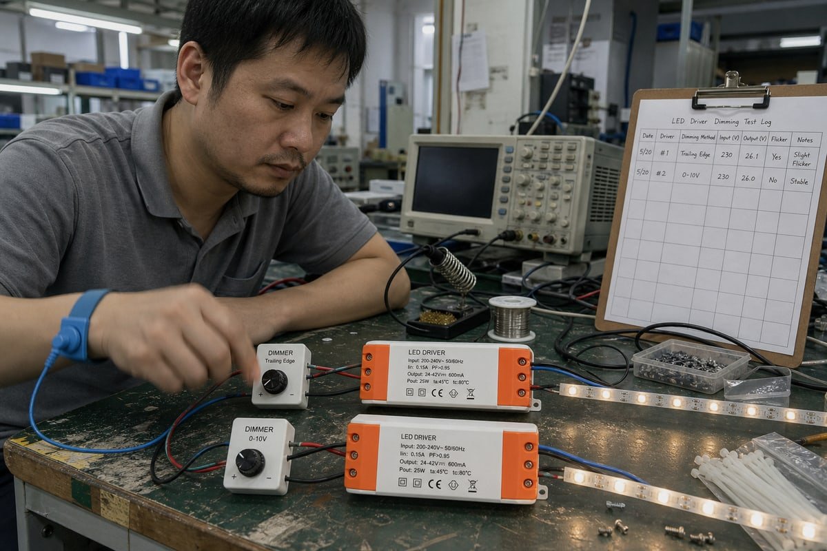
การเลือกระหว่าง leading-edge vs trailing-edge สำหรับ CC drivers ทำให้การเปิดตัวผลิตภัณฑ์ของลูกค้ารายหนึ่งของเราล่าช้าในปีที่แล้ว หากเลือกผิด ปัญหาการกะพริบจะท่วมท้น ห้องแล็บเซินเจิ้นของเราเห็นปัญหานี้ทุกสัปดาห์.
การหรี่แสงแบบ leading-edge ตัดช่วงเริ่มต้นของแต่ละครึ่งรอบไฟฟ้ากระแสสลับ ในขณะที่ trailing-edge ตัดช่วงท้าย คงที่กระแส LED ที่เข้ากันได้กับ phase-cut จะตรวจจับรูปคลื่นที่เหลือและควบคุมกระแส LED ตามนั้น ไม่มีวิธีใดที่ดีกว่าแบบสากล—ไดรเวอร์ต้องรองรับวิธีการหรี่แสงที่เลือกอย่างเฉพาะเจาะจงตลอดช่วงโหลดและช่วงการหรี่แสงที่ต้องการ.
คำตอบสั้นๆ นั้นซ่อนรายละเอียดทางวิศวกรรมไว้มากมาย ด้านล่างนี้ ผมจะอธิบายว่าแต่ละวิธีทำงานอย่างไร วิธีใดเหมาะกับสายผลิตภัณฑ์ของคุณ วิธีหลีกเลี่ยงความล้มเหลวด้านความเข้ากันได้ และการพัฒนาที่กำหนดเองทำงานอย่างไรสำหรับแบรนด์ private-label.
การหรี่แสงแบบ leading-edge และ trailing-edge แตกต่างกันอย่างไรสำหรับ CC drivers?
ในระหว่างการตรวจสอบ QC ล่าสุดที่โรงงานของเรา ตัวหรี่แสงสองตัวที่ดูเหมือนกันให้พฤติกรรมช่วงปลายต่ำที่แตกต่างกันโดยสิ้นเชิงบนไดรเวอร์เดียวกัน ความแตกต่างมาจากส่วนของรูปคลื่นที่ถูกตัด.
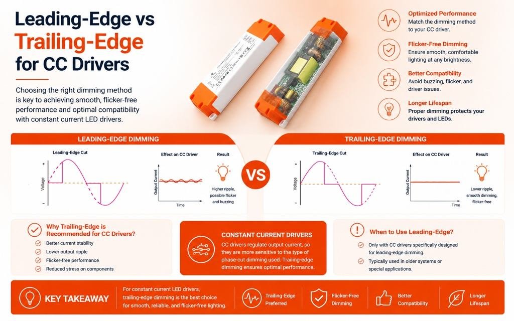
สำหรับไดรเวอร์คงที่กระแสที่หรี่แสงแบบ phase-cut ได้ การหรี่แสงแบบ leading-edge จะลบจุดเริ่มต้นของแต่ละครึ่งรอบไฟฟ้ากระแสสลับโดยใช้ TRIAC ในขณะที่ trailing-edge ลบจุดสิ้นสุดโดยใช้ MOSFET ไดรเวอร์อ่านมุมการนำไฟฟ้าที่เหลือและตั้งค่ากระแส LED ตามอัลกอริทึมการควบคุมของตัวเอง.
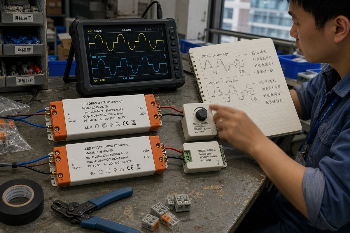
เทคโนโลยี phase-cut ไม่ใช่คำศัพท์ทางการตลาด มันอธิบายอย่างแม่นยำว่าคลื่นไซน์ไฟฟ้ากระแสสลับถูกตัดอย่างไรก่อนถึงไดรเวอร์ นี่คือการเปรียบเทียบหลักโดยสรุป:
| ลักษณะเฉพาะ | Leading-edge (เฟสไปข้างหน้า) | Trailing-edge (เฟสย้อนกลับ) |
|---|---|---|
| ชื่ออื่น | Forward-phase | Reverse-phase |
| การตัดรูปคลื่น | จุดเริ่มต้นของแต่ละครึ่งรอบ | ปลายของแต่ละครึ่งรอบ |
| สวิตช์ทั่วไป | ไทรแอก | MOSFET/สวิตช์อิเล็กทรอนิกส์ |
| โหลดทางประวัติศาสตร์ทั่วไป | หลอดไส้, ฮาโลเจน, แม่เหล็ก (โหลดเหนี่ยวนำ) | ไดรเวอร์อิเล็กทรอนิกส์, โหลด capacitive |
| ความเข้ากันได้กับ LED CC | ต้องระบุอย่างเฉพาะเจาะจง | ต้องระบุอย่างเฉพาะเจาะจง |
| ข้อกังวลทั่วไป | กระแสไฟกระชาก, เสียงอะคูสติก, โหลดขั้นต่ำ | ความเข้ากันได้ของไดรเวอร์, พฤติกรรมการควบคุม |
เกิดอะไรขึ้นภายในรูปคลื่น
ตัวหรี่แสงแบบ leading-edge ใช้ การหรี่แสงแบบ TRIAC, ซึ่งเป็นรูปแบบหนึ่งของการควบคุม forward-phase พวกมันรอหลังจุดตัดศูนย์ จากนั้นเปิดอย่างฉับพลัน ขอบแข็งนั้นสร้างแรงดันไฟกระชากและกระแสไฟกระชากที่คมชัด ตัวหรี่แสงแบบ trailing-edge ใช้การหรี่แสงแบบ reverse-phase ผ่าน MOSFET พวกมันนำไฟฟ้าตั้งแต่เริ่มต้นของครึ่งรอบและปิดอย่างนุ่มนวลก่อนสิ้นสุด การเปลี่ยนผ่านที่นุ่มนวลกว่า ดังนั้น EMI และเสียงหึ่งที่ได้ยินจึงมักจะต่ำกว่า.
ทำไมไดรเวอร์ ไม่ใช่ตัวหรี่แสง จึงเป็นตัวกำหนดกระแส
นี่คือจุดที่บทความส่วนใหญ่พลาด รูปคลื่น phase-cut ไม่เคยถูกส่งไปยัง LED โดยตรง ห่วงโซ่จริงคือ: ไฟฟ้ากระแสสลับหลัก → ตัวหรี่แสง phase-cut → ขั้นอินพุตของ CC driver → วงจรควบคุม → กระแส LED ที่ถูกควบคุม → LED ไดรเวอร์วัด มุมการนำไฟฟ้า 1 และแปลงเป็นคำสั่งกระแส ดังนั้นมุมเฟส 40% ไม่ได้หมายความว่ากระแส LED เป็น 40% โดยอัตโนมัติ อัลกอริทึมการควบคุมของไดรเวอร์เป็นตัวกำหนดการแมปนั้น ในการออกแบบของเราเอง เราปรับเส้นโค้งนั้นอย่างตั้งใจเพื่อให้ความสว่างรู้สึกนุ่มนวลต่อสายตามนุษย์.
ฉันควรเลือกประเภทการหรี่แสงแบบใดสำหรับสายผลิตภัณฑ์ LED ของฉัน?
ทุกสัปดาห์ผมชั่งน้ำหนักข้อแลกเปลี่ยนเดียวกันกับผู้ซื้อ: trailing-edge ให้ประสิทธิภาพที่นุ่มนวลกว่าบนไดรเวอร์สมัยใหม่ แต่ leading-edge ปกป้องงบประมาณเมื่อโครงการต้องใช้โครงสร้างพื้นฐาน TRIAC ที่ติดตั้งไว้แล้ว.
เลือกประเภทการหรี่แสงที่ข้อกำหนดไดรเวอร์ของคุณรองรับ ไม่ใช่กฎง่ายๆ Trailing-edge เหมาะกับ CC drivers อิเล็กทรอนิกส์สมัยใหม่ส่วนใหญ่และวงจรวัตต์ต่ำ leading-edge เหมาะกับระบบนิเวศ TRIAC แบบเดิมและการติดตั้งทดแทน ตรวจสอบโหลดขั้นต่ำ กระแสหรี่แสงขั้นต่ำ และช่วงมุมการนำไฟฟ้าก่อนตัดสินใจเลือกวิธีใดวิธีหนึ่ง.

ขอพูดตรงๆ เกี่ยวกับความเชื่อทางเทคนิคที่พบบ่อย Trailing-edge ไม่ได้ดีกว่าโดยเนื้อแท้เพียงเพราะการเปลี่ยนผ่านการสลับที่นุ่มนวลกว่า ในทางปฏิบัติ สถาปัตยกรรมอินพุตของไดรเวอร์ ความเข้ากันได้ของตัวหรี่แสง ข้อกำหนดโหลดขั้นต่ำ และกลยุทธ์การควบคุมสำคัญกว่าวิธี phase-cut เพียงอย่างเดียว ผมเคยเห็นระบบที่ตัวหรี่แสง trailing-edge ที่ supposedly ดีกว่าทำงานแย่กว่าตัวหรี่แสง leading-edge เพราะวงจรอินพุตของ CC driver ถูกปรับให้เหมาะสมสำหรับการทำงาน forward-phase TRIAC โดยเฉพาะ.
กระบวนการเลือกที่ถูกต้องเป็นดังนี้:
- ตรวจสอบข้อกำหนดไดรเวอร์ก่อน.
- ยืนยันประเภทการตัดเฟสที่รองรับ.
- ตรวจสอบความเข้ากันได้ของตัวหรี่ไฟจากรายการที่ผ่านการทดสอบ.
- จับคู่โหลดขั้นต่ำและสูงสุด.
- ยืนยันว่าช่วงการหรี่ไฟที่ต้องการได้รับการรับประกัน.
หมายเหตุ: LED = ขอบตัดด้านท้าย (trailing edge).
แต่ละวิธีมักจะชนะในจุดใด
| สถานการณ์ | ตัวเลือกที่เหมาะสมกว่า | เหตุผล |
|---|---|---|
| การปรับปรุงระบบด้วย TRIAC dimmer ที่ติดตั้งอยู่แล้ว | Leading-edge (เฟสไปข้างหน้า) | ใช้ระบบควบคุมเดิมที่มีอยู่; เป็นทางเลือกที่ถูกที่สุดเมื่อไดรเวอร์ได้รับการรับรองสำหรับการตัดเฟสด้านหน้า |
| วงจรไฟฟ้ากำลังต่ำต่ำกว่า 25W | Trailing-edge (เฟสย้อนกลับ) | Leading-edge dimmer มักต้องการโหลดขั้นต่ำ 25W–40W ซึ่งอาจทำให้เกิดการกะพริบหรือแสงกระตุกเมื่อต่ำกว่านั้น |
| โครงการที่ต้องการการหรี่ไฟลึก | Trailing-edge (เฟสย้อนกลับ) | สามารถถึงประมาณ 1% อย่างเสถียร; การออกแบบที่ใช้ GaN สามารถลดลงต่ำกว่า 0.1% |
| กลุ่มผลิตภัณฑ์ราคาประหยัดสำหรับที่พักอาศัย | Leading-edge (เฟสไปข้างหน้า) | ตัวหรี่ไฟมีราคาถูกกว่าและหาซื้อได้ทั่วไป |
| โรงแรมระดับพรีเมียมหรือร้านค้าปลีก | Trailing-edge (เฟสย้อนกลับ) | เส้นโค้งที่นุ่มนวลกว่า เสียงรบกวนต่ำกว่า ประสิทธิภาพไร้การกะพริบที่ระดับแสงต่ำ |
กับดักช่วงปลายต่ำ
ความล้มเหลวส่วนใหญ่ปรากฏที่ความสว่างต่ำกว่า 10–20% ระบบอาจดูสมบูรณ์แบบจาก 100% ลงไปถึง 50% จากนั้นเริ่มเกิดการกะพริบ ไฟดับ ไฟกระพริบ หรือโซนตายเมื่อมุมการนำไฟฟ้าหดเล็กลง โปรดจำไว้ว่าโหลด LED ขั้นต่ำและกระแสหรี่ขั้นต่ำเป็นข้อกำหนดที่แตกต่างกันสองอย่าง ไดรเวอร์อาจจ่ายโหลด 350 mA ได้อย่างสมบูรณ์แบบที่เอาต์พุตเต็ม แต่สูญเสียการควบคุมใกล้ขีดจำกัดล่าง ยังมีมุมมองเรื่องอายุการใช้งาน: การกระชาก dV/dt ที่รุนแรงของการทำงานแบบ leading-edge จะสร้างความเครียดให้กับตัวเก็บประจุไฟฟ้าอิเล็กโทรไลต์ที่อินพุตของไดรเวอร์ และข้อมูลในอุตสาหกรรมบางส่วนชี้ว่าสิ่งนี้อาจลดอายุการใช้งานของไดรเวอร์ได้ถึง 30% เมื่อเทียบกับการทำงานแบบ trailing-edge เรื่องนี้สำคัญเมื่อแบรนด์ของคุณรับผิดชอบการรับประกัน.
CC drivers แบบ trailing-edge จะทำให้เกิดปัญหาความเข้ากันได้กับสวิตช์หรี่แสงที่มีอยู่หรือไม่?
ผู้จัดการฝ่ายจัดซื้อในสิงคโปร์เคยส่งข้อความหาผมทาง WhatsApp พร้อมรูปไฟที่ยังเรืองแสงในทางเดินโรงแรมที่สร้างเสร็จแล้ว สาเหตุมาจากตัวหรี่ไฟที่ไม่เข้ากัน ไม่ใช่ไดรเวอร์ที่เสีย.
ไดรเวอร์ CC แบบ trailing-edge อาจทำให้เกิดปัญหากับวงจร TRIAC dimmer แบบเก่า แต่ปัญหาสามารถหลีกเลี่ยงได้ ไดรเวอร์แบบ universal phase-cut ที่มีการตรวจจับอัตโนมัติรองรับทั้งการควบคุมเฟสแบบไปข้างหน้าและย้อนกลับ ควรทดสอบคู่ไดรเวอร์-ตัวหรี่ไฟที่แน่นอนเสมอ ตรวจสอบข้อกำหนดโหลดขั้นต่ำ และปฏิบัติตามรายการความเข้ากันได้ของผู้ผลิต.
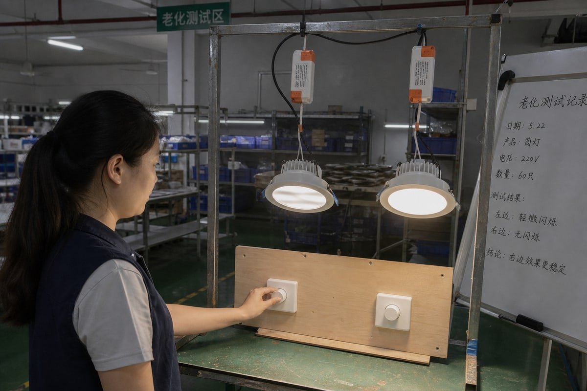
ความเข้ากันได้คือจุดที่โครงการจะสำเร็จหรือล้มเหลว และป้าย “หรี่ไฟได้” บนกล่องไม่เคยเพียงพอ อาการที่แตกต่างกันบ่งชี้ความไม่เข้ากันที่แตกต่างกัน ดังนั้นผมจึงเริ่มแก้ไขปัญหาจากตารางนี้เสมอ:
| อาการ | สาเหตุที่เป็นไปได้ | วิธีแก้ไขในทางปฏิบัติ |
|---|---|---|
| การกะพริบที่ระดับต่ำ | มุมการนำไฟฟ้าต่ำกว่าค่าขั้นต่ำของไดรเวอร์ | เพิ่มการปรับระดับต่ำสุดของตัวหรี่ไฟ หรือเลือกไดรเวอร์ที่มีกระแสหรี่ขั้นต่ำต่ำกว่า |
| เสียงฮัมที่ได้ยิน | การสวิตช์ TRIAC ที่รุนแรงกระตุ้นชิ้นส่วนภายในไดรเวอร์ | เปลี่ยนไปใช้การหรี่แบบ reverse phase หรือไดรเวอร์ที่รองรับการหน่วงสำหรับ forward phase |
| ไฟยังเรืองแสงเมื่อปิด | กระแสรั่วไหลผ่านตัวหรี่ไฟ | ใช้ไดรเวอร์ที่มีการหน่วงแบบปรับได้หรือการควบคุม bleeder |
| ตัวหรี่ไฟร้อนเกินไปหรือเสียหาย | กระแส inrush สะสมจากไดรเวอร์หลายตัว | ลดพิกัดของตัวหรี่ไฟหรือใช้ trailing-edge ที่มีพฤติกรรม soft-start |
| โซนตายบนปุ่มปรับ | เส้นโค้งของไดรเวอร์ไม่ตรงกับช่วงของตัวหรี่ไฟ | ปรับเทียบเส้นโค้งการหรี่ไฟที่ระดับไดรเวอร์ |
วงจรไดรเวอร์หลายตัวต้องการการดูแลเป็นพิเศษ
เมื่อไดรเวอร์ CC หลายตัวเชื่อมต่อกับ leading-edge dimmer หนึ่งตัว ทุก เหตุการณ์การยิง TRIAC 2 จะกระตุ้นกระแส inrush พร้อมกันจากโหลด capacitive ทั้งหมดในคราวเดียว ในกรณีรุนแรง การสะสมของกระแสไฟกระชากนี้อาจเชื่อมหน้าสัมผัสของตัวหรี่ไฟได้ MOSFET แบบ trailing-edge ช่วยลดปัญหานี้ผ่านคุณสมบัติ soft-start โดยธรรมชาติ และวงจร soft start ที่ออกแบบมาอย่างดีภายในไดรเวอร์ช่วยได้มากขึ้น นี่คือเหตุผลที่เรามักถามผู้ซื้อเสมอว่ามีไดรเวอร์กี่ตัวที่ใช้ตัวหรี่ไฟร่วมกันหนึ่งตัวก่อนที่จะเสนอโซลูชัน.
ไดรเวอร์สากลช่วยลดช่องว่าง
ไดรเวอร์ CC แบบ universal รุ่นใหม่ใช้ การประมวลผลสัญญาณดิจิทัล 3 เพื่อตรวจจับวิธีการตัดเฟสอัตโนมัติและปรับการหน่วงภายในแบบเรียลไทม์ ซึ่งช่วยกำจัดปัญหาไฟเรืองแสงได้เช่นกัน ลดความเสี่ยงได้ แต่ไม่ใช่เวทมนตร์ โหลดขั้นต่ำ คุณภาพของตัวหรี่ไฟ และสภาพการเดินสายยังคงเป็นตัวกำหนดผลลัพธ์ ดังนั้นเราจึงทดสอบไดรเวอร์ ELV แบบหรี่ได้ทุกตัวกับรุ่นตัวหรี่ไฟจริงของผู้ซื้อก่อนจัดส่ง บางครั้งคำตอบที่ถูกที่สุดสำหรับการปรับปรุงระบบคือการคง leading-edge dimmer เดิมไว้และระบุไดรเวอร์ที่ได้รับการรับรองสำหรับมัน.
ฉันสามารถขอ CC drivers แบบ leading-edge หรือ trailing-edge ที่กำหนดเองสำหรับแบรนด์ private-label ของฉันได้หรือไม่?
Early in our export business, we learned a hard lesson: shipping a standard driver into a market with an unfamiliar dimmer ecosystem creates returns. Custom development solves that upfront.
Yes. OEM/ODM suppliers can build leading-edge, trailing-edge, or universal phase-cut CC drivers to your specification, including custom output current, dimming curve, minimum dimming level, casing, logo printing, and certifications such as CE, CB, SAA, and SELV. Expect sampling, dimmer compatibility testing, and QC validation before mass production.

Our own compact drivers—the white-and-orange units with screw terminals and printed เครื่องหมาย CE, CB, SAA และ SELV 4—เริ่มต้นจากโครงการ ODM สำหรับเจ้าของแบรนด์ในยุโรป เอเชียตะวันออกเฉียงใต้ และออสเตรเลีย ตัวเรือน รูปแบบฉลาก และแม้แต่เส้นโค้งการหรี่แสง ถูกออกแบบตามตลาดของผู้ซื้อแต่ละราย ประสบการณ์นั้นสอนเราว่ากระบวนการปรับแต่งอย่างจริงจังมีลักษณะอย่างไร และฉันจะแบ่งปันที่นี่เพื่อให้คุณใช้เป็นเกณฑ์เปรียบเทียบซัพพลายเออร์รายใดก็ได้.
ขั้นตอนการพัฒนา OEM/ODM ที่สมจริง
- กำหนดข้อกำหนด: กระแสเอาต์พุต ช่วงกำลังไฟ และประเภทการตัดเฟสที่รองรับ—แบบ leading-edge, reverse หรือ universal.
- ตรวจสอบระบบนิเวศของตัวหรี่แสงในตลาดเป้าหมาย การหรี่แสงแบบ TRIAC ยังคงครองการติดตั้งแบบเดิมจำนวนมาก ในขณะที่แบบ trailing-edge เป็นมาตรฐานสำหรับโครงการสมัยใหม่ระดับพรีเมียม.
- สร้างและทดสอบตัวอย่างกับรุ่นตัวหรี่แสงที่คุณระบุ ไม่ใช่รุ่นทั่วไป.
- ปรับแต่งเส้นโค้งการหรี่แสง กระแสหรี่ต่ำสุด และพฤติกรรมช่วงปลายล่างเพื่อประสิทธิภาพไร้การกะพริบ.
- ดำเนินการรับรองสำหรับตลาดปลายทาง เช่น SAA สำหรับออสเตรเลีย หรือ CE สำหรับสหภาพยุโรป.
- ผลิตชุดนำร่องพร้อมการควบคุมคุณภาพเต็มรูปแบบ จากนั้นจึงเริ่มการผลิตจำนวนมาก.
คำถามที่ซัพพลายเออร์ของคุณต้องตอบก่อนที่คุณจะเซ็นสัญญา
อย่ายอมรับคำตอบว่า “350 mA, หรี่แสงแบบ phase-cut ได้” เป็นคำตอบที่สมบูรณ์ ให้สอบถามกระแส LED ขั้นต่ำที่ควบคุมได้ มุมนำไฟฟ้าขั้นต่ำ การออกแบบรองรับแบบ leading-edge, trailing-edge หรือทั้งสองอย่าง โหลดขั้นต่ำที่ระบุ ช่วงการหรี่แสงที่รับประกัน และหลักฐานว่าตัวขับได้รับการทดสอบกับตัวหรี่แสงที่คุณตั้งใจใช้ ในขั้นตอนการสุ่มตัวอย่างของเรา เราบันทึกคำตอบทั้งหกข้อก่อนเริ่มทำแม่พิมพ์ สำหรับผู้ซื้อแบบ private-label ที่ต้องบริหารกำหนดเวลาที่กระชั้นและต้นทุนโครงการโดยรวม เอกสารนี้ป้องกันโหมดความล้มเหลวที่แพงที่สุด นั่นคือการเรียกคืนสินค้าหลังวางจำหน่าย.
บทสรุป
การเลือกแบบ leading-edge เทียบกับ trailing-edge สำหรับตัวขับกระแสคงที่เป็นการตัดสินใจเรื่องการจับคู่ ไม่ใช่ความชอบส่วนตัว ระบุทั้งคู่ร่วมกัน ตรวจสอบประสิทธิภาพช่วงปลายล่าง และเรียกร้องการทดสอบความเข้ากันได้ที่ผ่านการรับรองก่อนที่คุณจะตัดสินใจ.
เชิงอรรถ
มุมนำไฟฟ้าเป็นแนวคิดพื้นฐานของตัวหรี่แสงที่อธิบายว่าวงจรตัดเฟสควบคุมกำลังไฟฟ้าอย่างไร. ↩︎
TRIAC คืออุปกรณ์สวิตชิ่งเซมิคอนดักเตอร์ที่ทำหน้าที่ควบคุมการหรี่แสงแบบ leading-edge forward-phase. ↩︎
IEEE กำหนดมาตรฐานสำหรับวิธีการประมวลผลสัญญาณดิจิทัลที่ใช้ในวงจรตรวจจับการตัดเฟสขั้นสูง. ↩︎
IEC กำกับดูแลโครงการ CB Scheme และมาตรฐานความปลอดภัยเบื้องหลังเครื่องหมายรับรอง CE, SAA และ SELV. ↩︎