















Выбор между leading-edge и trailing-edge для CC-драйверов сорвал запуск одного из наших клиентов в прошлом году. Ошибётесь — и жалобы на мерцание хлынут потоком. Наша лаборатория в Шэньчжэне видит это еженедельно.
Leading-edge диммирование срезает начало каждого полупериода переменного тока, а trailing-edge срезает конец. Совместимый с фазовым срезом драйвер постоянного тока для светодиодов обнаруживает оставшуюся форму волны и регулирует ток светодиодов соответствующим образом. Ни один метод не является универсально лучшим — драйвер должен конкретно поддерживать выбранный метод диммирования в требуемом диапазоне нагрузки и диммирования.
Этот краткий ответ скрывает множество инженерных деталей. Ниже я разберу, как работает каждый метод, какой из них подходит для вашей линейки продуктов, как избежать сбоев совместимости и как работает индивидуальная разработка для частных марок.
Чем на самом деле отличаются leading-edge и trailing-edge диммирование для CC-драйверов?
Во время недавнего контроля качества на нашей фабрике два одинаковых на вид диммера показали совершенно разное поведение на нижнем пределе с одним и тем же драйвером. Разница сводилась к тому, какая часть формы волны была срезана.
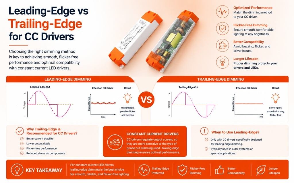
Для диммируемого драйвера постоянного тока с фазовым срезом leading-edge диммирование удаляет начало каждого полупериода переменного тока с помощью TRIAC, а trailing-edge удаляет конец с помощью MOSFET. Драйвер считывает оставшийся угол проводимости и задаёт ток светодиодов на основе собственного алгоритма управления.

Технология фазового среза — это не маркетинговый термин. Она точно описывает, как синусоида переменного тока обрезается до того, как достигает драйвера. Вот ключевое сравнение с первого взгляда:
| Особенность | Диммеры по переднему фронту | Диммеры по заднему фронту |
|---|---|---|
| Другое название | Прямая фаза | Обратная фаза |
| Срез формы волны | Начало каждого полупериода | Конец каждого полупериода |
| Обычный переключатель | TRIAC | MOSFET/электронный переключатель |
| Типичные исторические нагрузки | Лампы накаливания, галогенные, магнитные (индуктивные нагрузки) | Электронные драйверы, ёмкостные нагрузки |
| Совместимость с CC-светодиодами | Должна быть указана | Должна быть указана |
| Типичная проблема | Бросок тока, акустический шум, минимальная нагрузка | Совместимость драйвера, поведение управления |
Что происходит внутри формы волны
Leading-edge диммеры используют TRIAC-диммирование, форму forward-phase управления. Они ждут после перехода через ноль, затем резко включаются. Этот жёсткий фронт создаёт скачки напряжения и резкий бросок тока. Trailing-edge диммеры используют reverse-phase диммирование через MOSFET. Они проводят с начала полупериода и плавно выключаются перед концом. Переход мягче, поэтому ЭМП и слышимое гудение обычно ниже.
Почему драйвер, а не диммер, задаёт ток
Вот момент, который большинство статей упускают. форма волны с фазовым срезом никогда не подаётся на светодиоды напрямую. Реальная цепочка: сеть переменного тока → диммер с фазовым срезом → входной каскад CC-драйвера → схема управления → регулируемый ток светодиодов → светодиоды. Драйвер измеряет угол проводимости 1 и преобразует его в команду тока. Таким образом, фазовый угол 40% не означает автоматически ток светодиодов 40%. Алгоритм управления драйвера определяет это соответствие. В наших собственных конструкциях мы намеренно формируем эту кривую, чтобы яркость ощущалась плавной для человеческого глаза.
Какой тип диммирования мне выбрать для моей линейки светодиодных продуктов?
Каждую неделю я взвешиваю один и тот же компромисс с покупателями: trailing-edge даёт более плавную работу на современных драйверах, но leading-edge защищает бюджеты, когда проект должен использовать установленную инфраструктуру TRIAC.
Выбирайте тип диммирования, который поддерживает спецификация вашего драйвера, а не по общему правилу. Trailing-edge подходит для большинства современных электронных CC-драйверов и низковольтных схем; leading-edge подходит для устаревших экосистем TRIAC и модернизаций. Проверьте минимальную нагрузку, минимальный ток диммирования и диапазон угла проводимости перед выбором любого метода.

Позвольте мне быть прямым насчёт распространённого технического мифа. Trailing-edge не является inherently лучше только потому, что его переключение мягче. На практике входная архитектура драйвера, совместимость с диммером, требование минимальной нагрузки и стратегия управления важнее, чем сам метод фазового среза. Я видел системы, где supposedly лучший trailing-edge диммер работал хуже, чем leading-edge диммер, потому что входная схема CC-драйвера была специально оптимизирована для работы с forward-phase TRIAC.
Правильный процесс выбора выглядит так:
- Сначала проверьте спецификацию драйвера.
- Подтвердите поддерживаемый тип фазового управления.
- Проверьте совместимость диммера по протестированному списку.
- Согласуйте минимальную и максимальную нагрузку.
- Подтвердите, что требуемый диапазон диммирования гарантирован.
Примечание: LED = задний фронт.
Где каждый метод обычно выигрывает
| Сценарий | Лучшее соответствие | Почему |
|---|---|---|
| Модернизация с установленными TRIAC-диммерами | Диммеры по переднему фронту | Использует существующие системы управления; самый дешевый путь, если драйвер сертифицирован для переднего фронта |
| Низковольтные цепи до 25 Вт | Диммеры по заднему фронту | Диммеры с передним фронтом часто требуют минимальной нагрузки 25–40 Вт, что вызывает мерцание или стробоскопический эффект ниже этого значения |
| Проекты с глубоким диммированием | Диммеры по заднему фронту | Может стабильно достигать около 1%; конструкции на основе GaN опускаются ниже 0,1% |
| Бюджетные жилые линейки | Диммеры по переднему фронту | Диммеры дешевле и широко доступны |
| Премиальный сегмент гостиниц или розничной торговли | Диммеры по заднему фронту | Более плавная кривая, низкий уровень шума, отсутствие мерцания на низких уровнях |
Ловушка нижнего предела
Большинство отказов проявляются при яркости ниже 10–20%. Система может выглядеть идеально от 100% до 50%, а затем появляются мерцание, пропадание сигнала, вспышки или мертвая зона по мере уменьшения угла проводимости. Помните, что минимальная нагрузка LED и минимальный ток диммирования — это две разные характеристики. Драйвер может идеально работать с нагрузкой 350 мА при полной выходной мощности, но терять регулировку вблизи нижнего предела. Также есть аспект срока службы: жесткие скачки dV/dt при работе с передним фронтом нагружают входные электролитические конденсаторы драйвера, и некоторые отраслевые данные показывают, что это может сократить срок службы драйвера до 30% по сравнению с работой с задним фронтом. Это важно, когда ваш бренд несет гарантийные обязательства.
Вызовут ли trailing-edge CC-драйверы проблемы совместимости с существующими диммерными выключателями?
Менеджер по закупкам из Сингапура однажды написал мне в WhatsApp фото мерцающих светильников в готовом гостиничном коридоре. Причиной был неисправный диммер, а не драйвер.
Драйверы постоянного тока с задним фронтом могут вызывать проблемы на старых цепях с TRIAC-диммерами, но этих проблем можно избежать. Универсальные драйверы с фазовым управлением и автоматическим определением поддерживают как передний, так и задний фронт. Всегда тестируйте конкретную пару драйвер-диммер, проверяйте требование минимальной нагрузки и следуйте списку совместимости производителя.

Совместимость — это то, где проекты либо успешны, либо проваливаются, и надпись “диммируемый” на коробке никогда не является достаточной. Разные симптомы указывают на разные несоответствия, поэтому я всегда начинаю диагностику с этой таблицы:
| Симптом | Вероятная причина | Практическое решение |
|---|---|---|
| Мерцание на низких уровнях | Угол проводимости ниже минимального для драйвера | Поднимите нижний предел диммера или выберите драйвер с более низким минимальным током диммирования |
| Слышимый гул | Жесткое переключение TRIAC возбуждает компоненты драйвера | Переключитесь на диммирование с задним фронтом или драйвер с демпфированием для переднего фронта |
| Свечение в выключенном состоянии | Ток утечки через диммер | Используйте драйвер с адаптивным демпфированием или управлением нагрузкой |
| Перегрев или отказ диммера | Суммарный пусковой ток от нескольких драйверов | Снизьте нагрузку на диммер или используйте задний фронт с функцией мягкого запуска |
| Мертвая зона на регуляторе | Кривая драйвера не соответствует диапазону диммера | Перекалибруйте кривую диммирования на уровне драйвера |
Схемы с несколькими драйверами требуют особого внимания
Когда несколько драйверов постоянного тока подключены к одному диммеру с передним фронтом, каждое событие срабатывания TRIAC 2 вызывает одновременный пусковой ток от всех емкостных нагрузок сразу. В тяжелых случаях этот суммарный скачок может сварить контакты диммера. MOSFET-переключатели с задним фронтом смягчают это за счет своих встроенных характеристик мягкого запуска, а хорошо спроектированная схема мягкого запуска внутри драйвера помогает еще больше. Поэтому мы всегда спрашиваем покупателей, сколько драйверов подключено к одному диммеру, прежде чем предлагать решение.
Универсальные драйверы сокращают разрыв
Новые универсальные драйверы постоянного тока используют цифровую обработку сигналов 3 для автоматического определения метода фазового управления и перенастройки внутреннего демпфирования в реальном времени, что также помогает устранить свечение. Они снижают риск, но не являются волшебством. Минимальная нагрузка, качество диммера и условия проводки по-прежнему определяют результат, поэтому мы проводим стендовые испытания каждого диммируемого драйвера ELV с реальными моделями диммеров покупателя перед отгрузкой. Иногда самое дешевое решение для модернизации — просто сохранить существующий диммер с передним фронтом и указать драйвер, сертифицированный для него.
Могу ли я получить индивидуальные leading-edge или trailing-edge CC-драйверы для моего частного бренда?
В начале нашего экспортного бизнеса мы усвоили жесткий урок: отправка стандартного драйвера на рынок с незнакомой экосистемой диммеров приводит к возвратам. Индивидуальная разработка решает эту проблему на начальном этапе.
Да. Поставщики OEM/ODM могут производить драйверы постоянного тока с передним фронтом, задним фронтом или универсальным фазовым управлением по вашей спецификации, включая индивидуальный выходной ток, кривую диммирования, минимальный уровень диммирования, корпус, печать логотипа и сертификаты, такие как CE, CB, SAA и SELV. Ожидайте предоставление образцов, тестирование совместимости с диммерами и контроль качества перед массовым производством.

Наши собственные компактные драйверы — бело-оранжевые блоки с винтовыми клеммами и напечатанными знаками CE, CB, SAA и SELV 4—начинали как ODM-проекты для брендовых владельцев в Европе, Юго-Восточной Азии и Австралии. Корпус, макет этикетки и даже кривая диммирования были сформированы под рынок каждого покупателя. Этот опыт научил нас тому, как выглядит серьезный процесс кастомизации, и я поделюсь им здесь, чтобы вы могли оценить любого поставщика.
Реалистичный процесс разработки OEM/ODM
- Определите спецификацию: выходной ток, диапазон мощности и поддерживаемый тип фазового управления — передний фронт, задний фронт или универсальный.
- Изучите экосистему диммеров целевого рынка; TRIAC-диммирование по-прежнему доминирует во многих устаревших установках, тогда как управление по заднему фронту является стандартом для современных премиальных проектов.
- Создавайте и тестируйте образцы на ваших конкретных моделях диммеров, а не на универсальных.
- Настройте кривую диммирования, минимальный ток диммирования и поведение на нижнем пределе для бесмерцающей работы.
- Пройдите сертификацию для целевого рынка, например SAA для Австралии или CE для ЕС.
- Запустите пилотную партию с полным контролем качества, затем выпустите массовое производство.
Вопросы, на которые поставщик должен ответить до подписания контракта
Не принимайте “350 мА, фазовое диммирование” как полный ответ. Запросите минимальный регулируемый ток светодиодов, минимальный угол проводимости на входе, поддерживает ли конструкция передний фронт, задний фронт или оба, указанную минимальную нагрузку, гарантированный диапазон диммирования и подтверждение того, что драйвер был протестирован с вашим предполагаемым диммером. На этапе выборки мы документируем все шесть ответов до начала оснастки. Для покупателей под частной маркой, работающих в условиях жестких сроков и общей стоимости проекта, такая документация предотвращает самый дорогостоящий сбой: отзыв после запуска.
Заключение
Передний фронт против заднего фронта для CC-драйверов — это решение о совместимости, а не предпочтение. Укажите пару вместе, проверьте работу на нижнем пределе и требуйте подтвержденной совместимости до принятия обязательств.
Сноски
Угол проводимости — это фундаментальная концепция диммера, объясняющая, как схемы фазового управления регулируют мощность. ↩︎
TRIAC — это полупроводниковый переключающий элемент, выполняющий управление диммированием по переднему фронту. ↩︎
IEEE устанавливает стандарты для методов цифровой обработки сигналов, используемых в продвинутых схемах обнаружения фазового управления. ↩︎
IEC контролирует схему CB и стандарты безопасности, лежащие в основе сертификационных знаков CE, SAA и SELV. ↩︎