















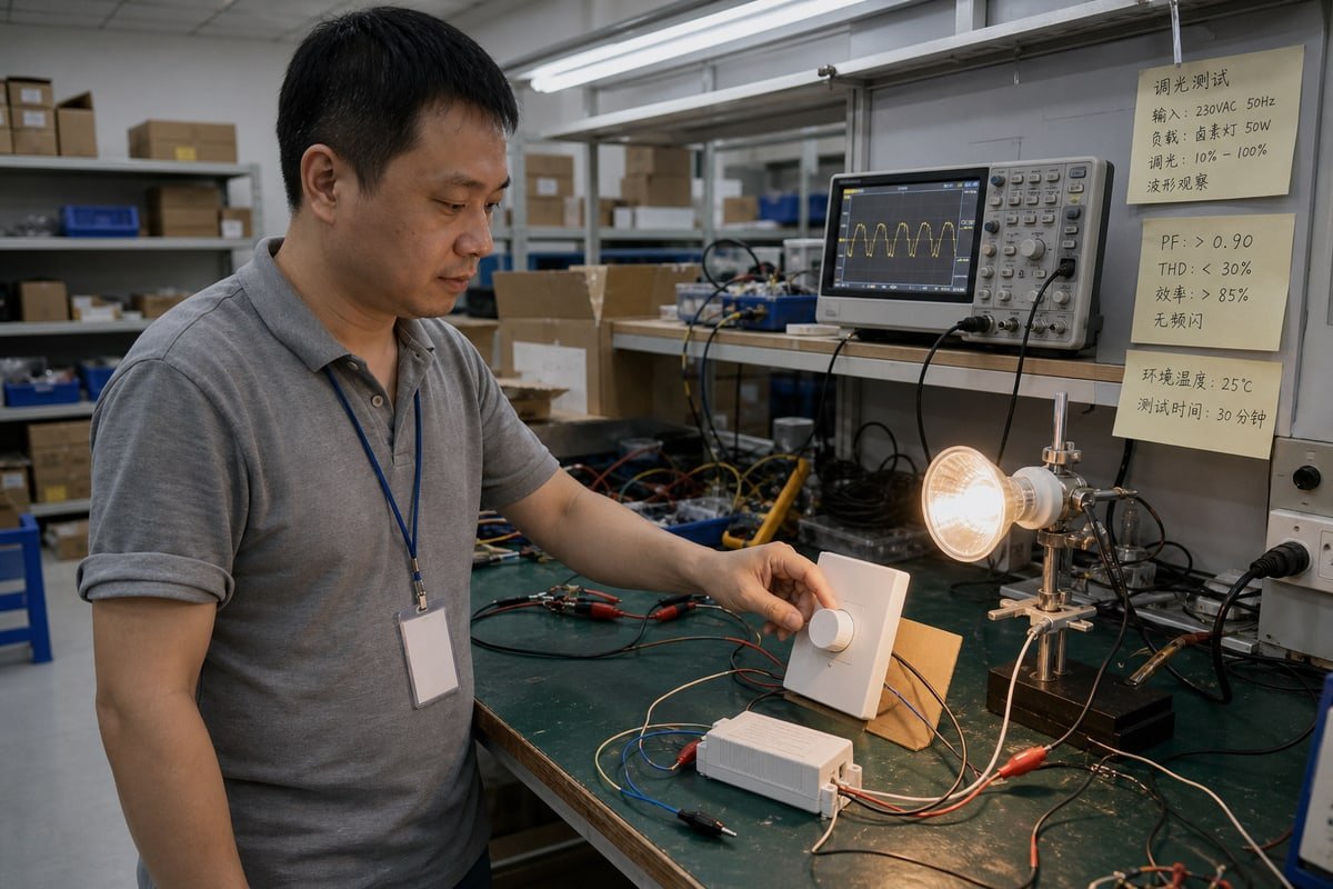
Cada semana, los compradores envían correos electrónicos a nuestro laboratorio en Shenzhen sobre un atenuador de borde delantero 1 que hace parpadear los LED. Las devoluciones se acumulan, los plazos se retrasan y los márgenes se reducen. La solución comienza con la comprensión de la tecnología.
Un regulador de borde delantero es un atenuador de corte de fase de CA que reduce la salida de luz al apagar el inicio de cada semiciclo de voltaje de CA. Construido alrededor de tecnología TRIAC o tiristor, fue diseñado principalmente para cargas incandescentes y halógenas y solo es adecuado para controladores LED clasificados para ello.
Esa definición cubre lo básico. Pero las preguntas reales de ingeniería están debajo. ¿Cómo ocurre realmente el recorte de la forma de onda? ¿En qué se diferencia del control de borde trasero? ¿Y qué cargas puede conectar de manera segura? Explicaré cada pregunta a continuación, utilizando lo que vemos en nuestros propios bancos de pruebas todos los días.
¿Cómo funciona realmente un atenuador de borde delantero?
En nuestro banco de pruebas, disparamos cada muestra de atenuador en un rango completo de cargas antes de que se envíe. Ese hábito nos enseñó exactamente qué sucede dentro de cada medio ciclo.
Un atenuador de borde delantero retrasa el punto de encendido del TRIAC después de cada cruce por cero de la onda senoidal de CA. Bloquea el frente de cada medio ciclo y luego conduce el resto, lo que reduce la potencia promedio que llega a la lámpara y atenúa la luz.
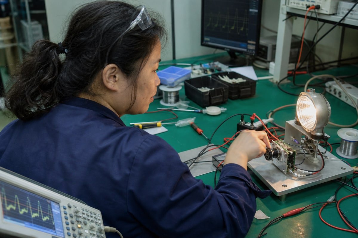
Por eso este método también se llama control de fase directa. El atenuador recorta el borde frontal de la forma de onda, por lo que llega menos energía a la lámpara por ciclo. Su ojo lo interpreta como menor brillo. Permítame desglosar la secuencia.
La secuencia de disparo, paso a paso
- La onda senoidal de CA cruza cero voltios.
- El circuito de control del atenuador espera un retraso establecido. Girar la perilla cambia este retraso, conocido como ángulo de disparo.
- Un pulso de compuerta dispara el TRIAC, o en algunos diseños un Rectificador Controlado de Silicio (SCR).
- El TRIAC conduce el resto del medio ciclo y entrega potencia a la carga.
- La corriente cae por debajo del umbral de mantenimiento del TRIAC en el siguiente cruce por cero. El dispositivo se apaga por sí solo, y el ciclo se repite cien o más veces por segundo.
Lo que el encendido abrupto hace aguas abajo
Ese encendido repentino a mitad de ciclo no es suave. El voltaje salta casi instantáneamente, lo que crea un pico de dV/dt alto. En nuestras pruebas de EMI, vemos que esos picos generan ruido eléctrico 2, y en el campo pueden causar disparos molestos en los interruptores AFCI modernos. Hay otro problema de envejecimiento que vale la pena conocer. Cuando un atenuador más antiguo dispara de manera asimétrica entre medios ciclos, introduce un desplazamiento de CC en la línea, lo que puede saturar y sobrecalentar transformadores en equipos cercanos. Estos son los comportamientos ocultos que una definición simple nunca menciona, y importan cuando especifica Regulación de intensidad con TRIAC a escala.
¿Cuál es la diferencia entre atenuadores de borde delantero y borde trasero?
La presión de precio frente a la suavidad de atenuación es una compensación que discuto con casi todos los distribuidores que nos hacen pedidos. Las dos familias de recorte de fase se encuentran en lados opuestos de esto.
Los reguladores de borde delantero cortan el inicio de cada semiciclo de CA mediante conmutación TRIAC o tiristor, mientras que los reguladores de borde trasero cortan el final utilizando electrónica basada en MOSFET. Los modelos de borde trasero suelen atenuar los controladores LED compatibles de manera más suave y silenciosa; el borde delantero es adecuado para cargas resistivas e inductivas magnéticas.

Aquí está la vista comparativa que comparto con los equipos de compras antes de que elijan un estándar para un proyecto:
| Rasgo | Borde Delantero | Borde Trasero |
|---|---|---|
| Forma de onda | Corta el comienzo de cada medio ciclo | Corta el final de cada medio ciclo |
| Tecnología común | TRIAC/tiristor | A menudo conmutación MOSFET/electrónica |
| Aplicación histórica | Incandescente/halógena | Bajo voltaje electrónico y muchas cargas modernas |
| Compatibilidad con LED | Dependiente del controlador | A menudo ventajoso para controladores LED compatibles |
| Rendimiento LED de gama baja | Puede ser desafiante | A menudo más suave, pero dependiente del controlador |
| Preocupación clave | Carga mínima, corriente de mantenimiento, corriente de irrupción | Compatibilidad del controlador y comportamiento electrónico |
¿Es el borde trasero simplemente mejor?
Muchas guías dicen que sí, y los compradores plantean esta objeción constantemente. Mi respuesta es no, no automáticamente. Un atenuador de borde trasero reduce el voltaje suavemente al final de cada medio ciclo, lo que reduce el parpadeo y el zumbido que afectan a las instalaciones LED mal emparejadas. Pero el borde delantero sigue siendo la opción correcta para las cargas para las que fue diseñado, incluidas las bombillas incandescentes y halógenas y los transformadores magnéticos, que son cargas inductivas que toleran bien el encendido abrupto.
La regla que realmente importa
Ambos enfoques son atenuación por corte de fase. Ninguna etiqueta garantiza por sí sola el rendimiento del LED. Lo que decide el resultado es si la etapa de entrada del driver LED fue diseñada para esa forma de onda recortada específica. Cuando desarrollamos pares de driver y regulador para clientes OEM, los emparejamos como un sistema, no como dos partes independientes. Esa mentalidad previene la mayoría de las quejas de campo antes de que ocurran.
¿Qué cargas de iluminación son compatibles con un regulador de borde delantero?
Un gerente de compras en Singapur me escribió una vez por WhatsApp con fotos de downlights brillando en estado "apagado". Sus luminarias eran regulables, pero el emparejamiento seguía fallando.
Los reguladores de fase de borde delantero son adecuados para cargas resistivas como bombillas incandescentes y halógenas, además de transformadores magnéticos de bajo voltaje. Los LED solo funcionan cuando el driver LED está específicamente clasificado para atenuación por corte de fase TRIAC; los drivers no clasificados pueden parpadear, zumbar, atenuar deficientemente o permanecer parcialmente encendidos al apagarse.
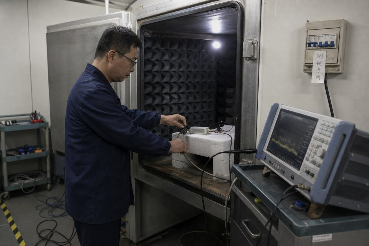
Ese caso de WhatsApp captura todo el problema de compatibilidad. Sus lámparas estaban etiquetadas como regulables. La clasificación de potencia 3 del regulador cubría las luminarias. El sistema seguía comportándose mal. Aquí está el panorama carga por carga:
| Tipo de carga | Compatibilidad | Notas |
|---|---|---|
| Bombillas incandescentes | Excelente | Carga resistiva predecible; la combinación clásica |
| Bombillas halógenas | Excelente | También resistivas; regulación suave de rango completo |
| Transformadores magnéticos de bajo voltaje | Bueno | Cargas inductivas que el borde delantero maneja bien |
| Drivers LED clasificados para TRIAC | Condicional | Deben estar explícitamente clasificados para regulación de borde delantero |
| LEDs "regulables" genéricos | Riesgoso | La etapa de entrada del driver puede no tolerar la forma de onda recortada |
| LEDs/CFLs no regulables | Incompatible | Espere fallos o daños |
Dentro de un controlador LED moderno
Un filamento incandescente es una carga resistiva simple. Un driver LED no lo es. Puede contener un rectificador, capacitor de gran valor, convertidor conmutado, filtro EMI y circuitos de control. Un regulador TRIAC de borde delantero interactúa con esa capacitancia de entrada 4 y con el requisito de corriente de mantenimiento del TRIAC. Cuando la combinación es incorrecta, vemos parpadeo en niveles bajos de regulación, disparo erróneo o caída del TRIAC, zumbido audible, un rango de regulación útil estrecho, LEDs que permanecen parcialmente encendidos en "apagado" y comportamiento diferente cuando varios drivers comparten un solo regulador. La distorsión armónica por corte de fase puede incluso confundir a los drivers dim-to-warm, causando cambios de color inconsistentes.
La trampa de la carga mínima
Los reguladores tradicionales de borde delantero suelen tener un requisito de carga mínima de aproximadamente 25W–60W. Una carga LED pequeña consume mucho menos corriente que la carga incandescente que el regulador esperaba, por lo que la combinación se vuelve inestable incluso dentro de la clasificación de potencia. Mi regla B2B: verifique si el driver LED, no solo la lámpara, está clasificado para regulación de borde delantero, y confirme los requisitos de carga mínima, carga máxima y corriente de irrupción.
¿Por qué elegiría un regulador de borde líder para mi próximo pedido al por mayor?
Años de proyectos OEM me enseñaron que las decisiones de compra de reguladores fallan en la hoja de especificaciones, no en la planta de producción. Los pedidos de gran volumen magnifican cada detalle de compatibilidad pasado por alto.
Elija un regulador de fase de borde delantero para pedidos al por mayor cuando su base instalada utilice controladores LED con lámparas incandescentes, halógenas o clasificados para TRIAC, cuando los presupuestos sean ajustados o al reemplazar reguladores de pared antiguos. Verifique la carga mínima, la carga máxima, la corriente de irrupción y el rendimiento de apagado real antes de comprometerse con el volumen.

Existen razones comerciales sólidas para estandarizar el borde delantero en ciertos proyectos. Estos reguladores son generalmente más asequibles y más disponibles que las alternativas de borde trasero. Siguen siendo el estándar heredado en millones de edificios antiguos, por lo que la demanda de modernización y reemplazo se mantiene estable en los mercados a los que enviamos, desde Singapur y Australia hasta Alemania y el Reino Unido. Para distribuidores que atienden proyectos hoteleros con carga halógena o propietarios que reemplazan reguladores de pared por equivalentes, el borde delantero suele ser la opción pragmática.
La lista de verificación previa al pedido
Antes de que cualquier cliente nuestro confirme un pedido de gran volumen, les explicamos esta lista:
| Elemento de verificación | Por qué es importante |
|---|---|
| Clasificación de regulación del driver | El driver, no la lámpara, debe estar clasificado para control TRIAC de borde delantero |
| Carga mínima | Cargas LED pequeñas por debajo de aproximadamente 25W–60W pueden desestabilizar el TRIAC |
| Carga máxima e irrupción | Los drivers LED generan picos de irrupción que estresan reguladores de tamaño insuficiente |
| Rango de atenuación | Confirme el rendimiento útil en el extremo bajo, no solo en el extremo alto |
| Comportamiento de apagado real | Las rutas de fuga pueden dejar LEDs brillando en "apagado" |
| Comportamiento con múltiples drivers | Varios drivers en un solo regulador se comportan de manera diferente a uno solo |
Cómo reducimos el riesgo antes del envío
Nuestro proceso es sencillo. Solicitamos el modelo exacto de la luminaria o el driver, luego probamos muestras emparejadas mediante regulación de rango completo, verificación de parpadeo en el extremo bajo y pruebas de apagado real antes de la producción en masa. Para clientes de marca privada con plazos ajustados, esta semana de validación previene meses de reclamaciones de garantía. También co-desarrollamos conjuntos emparejados de regulador y driver bajo el logotipo del cliente, lo que elimina por completo el riesgo de compatibilidad.
Conclusión
Un regulador de borde delantero sigue teniendo su lugar cuando se combina con la carga correcta. Verifique la compatibilidad del driver, la carga mínima y la corriente de irrupción, y sus pedidos a granel funcionarán de manera confiable.
Notas al pie
Descripción general autoritativa de las tecnologías de regulación y la historia de los controles de iluminación por corte de fase. ↩︎
Recurso federal que explica la interferencia electromagnética y el impacto del ruido eléctrico en los circuitos. ↩︎
La página de Wikipedia sobre Dimmer ofrece una explicación técnica detallada de las clasificaciones de potencia y vataje para sistemas de regulación por corte de fase. ↩︎
Entrada de enciclopedia científica que explica cómo la capacitancia afecta el comportamiento de los circuitos electrónicos y la entrega de energía. ↩︎