















Casi todas las semanas recibo en mi bandeja de entrada preguntas sobre la regulación por corte de fase. Los compradores me comentan que sus controladores LED “regulables” parpadean, emiten un zumbido o dejan de funcionar a niveles bajos. Ese fallo supone un coste económico real para los proyectos. Tras años fabricando controladores LED regulables en nuestras instalaciones de Shenzhen, quiero explicar cómo funciona realmente esta tecnología y cómo puedes sacarle el máximo partido.
La regulación por corte de fase es un método para controlar el brillo de los LED que consiste en cortar parte de la forma de onda de la tensión de CA antes de que llegue al controlador del LED. El regulador activa o desactiva la onda sinusoidal en un punto determinado de cada semiciclo, lo que reduce la potencia suministrada y atenúa la luz.
Esa breve respuesta resume la definición. Pero lo realmente importante está en los detalles. Déjame explicarte cómo funciona, por qué falla y cómo elegir el hardware adecuado.
¿Cómo funciona realmente la regulación por corte de fase en un controlador LED?
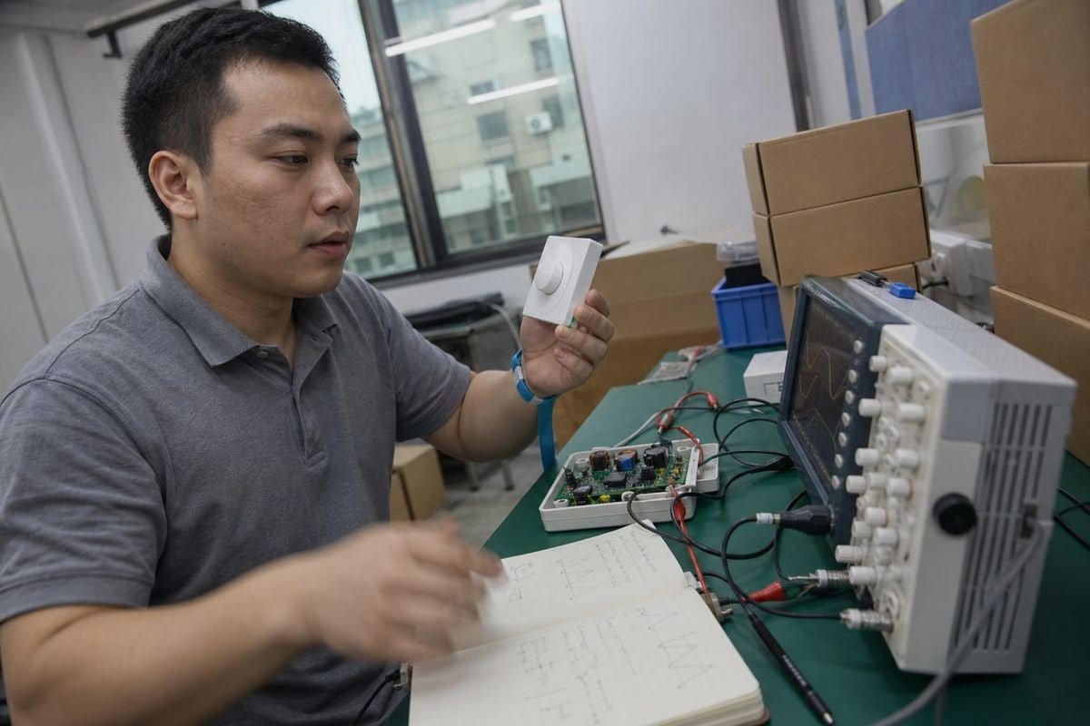
Cuando nuestros ingenieros prueban un nuevo diseño de controlador, lo primero que colocan en el banco de pruebas es un osciloscopio. Observar la forma de onda fragmentada nos dice más de lo que jamás podría indicar cualquier especificación técnica.
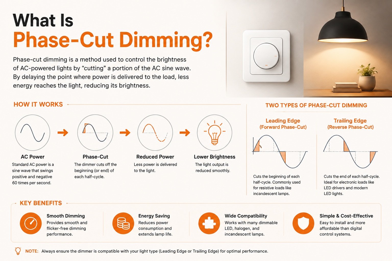
Un regulador de intensidad por corte de fase interrumpe cada semiciclo de la corriente alterna, retrasando o interrumpiendo la conducción. El controlador del LED lee esta forma de onda acortada, mide el ángulo de fase y la convierte en una corriente de salida constante proporcionalmente menor, lo que reduce el brillo del LED de forma suave y segura.

La alimentación de la red eléctrica es una onda sinusoidal de CA suave. Un regulador de intensidad con corte de fase no reduce esa tensión de forma suave y analógica. En su lugar, lleva a cabo una especie de modulación de onda sinusoidal 1: activa y desactiva la corriente en un punto preciso de cada semiciclo, dos veces por ciclo de red. La parte eliminada viene descrita por el ángulo de fase 2. Cuanto mayor es el recorte, menos energía llega a la carga, por lo que la luz se atenúa. En términos técnicos, el recorte de la forma de onda reduce la tensión y la potencia cuadrática media (RMS) totales que se suministran a la fuente de luz.
De una forma de onda entrecortada a una luz constante
Un filamento incandescente simplemente brillaba menos cuando recibía menos potencia. Un controlador de LED tiene una tarea más complicada. Debe tomar esa entrada irregular e interrumpida y, aun así, producir una corriente limpia y constante en el lado de salida. A continuación se explica el proceso en pasos sencillos:
- El regulador de intensidad corta la forma de onda de la corriente alterna en un ángulo de fase determinado.
- La parte delantera del controlador detecta qué parte de la forma de onda se ha eliminado.
- Los circuitos internos convierten ese ángulo de fase en un nivel de regulación de la intensidad luminosa.
- La etapa de salida suministra una corriente más baja y estable a los LED.
- Los LED se atenúan sin parpadeos visibles, siempre que todo sea compatible.
El paso 2 es donde empiezan la mayoría de los problemas. Si el controlador interpreta mal la forma de onda, la luz resulta inestable. Por eso, el diseño de la entrada del controlador es tan importante como el propio regulador.
¿Por qué este método sigue utilizándose en los proyectos actuales?
La regulación por corte de fase funciona con el cableado de dos hilos ya existente. No hay ningún cable de control independiente, a diferencia de 0-10 V o DALI sistemas. En el caso de los proyectos de adaptación en viviendas, hoteles y espacios hosteleros, esto se traduce en un menor coste de instalación y en controles de pared con los que ya se está familiarizado. Cuando Olivia, una responsable de compras con la que colaboramos en Singapur, especifica controladores para focos empotrados en proyectos de adaptación, la compatibilidad con el cableado de dos hilos suele ser su primer requisito, ya que el cableado ya está instalado en la pared.
¿Por qué se produce un parpadeo o un zumbido al utilizar reguladores de fase con controladores LED?
Un distribuidor italiano nos envió una vez una caja con reguladores de intensidad que sus clientes habían devuelto. Todos funcionaban perfectamente; el problema eran los controladores con los que se habían emparejado, que no eran compatibles. Esa caja nos enseñó a nuestro equipo una lección que no olvidaremos nunca sobre las pruebas de compatibilidad.
El parpadeo y el zumbido suelen deberse a una incompatibilidad eléctrica entre el regulador de intensidad y el controlador LED. Entre las causas más comunes se encuentran una corriente de mantenimiento insuficiente en el caso de un regulador TRIAC, el incumplimiento de los requisitos mínimos de carga, picos de corriente de arranque y controladores que interpretan erróneamente la forma de onda modulada.

Un controlador con la etiqueta “regulable mediante TRIAC” puede seguir parpadeando, emitir un zumbido, presentar recorrido muerto o no permitir la regulación por debajo de un determinado nivel. La etiqueta describe la finalidad, no un rendimiento garantizado. El rendimiento real depende de la combinación específica del tipo de regulador, el diseño del controlador y la carga del LED. En otras palabras, “regulable” no significa “compatible con reguladores”.”
Los principales modos de fallo y sus causas
| Síntoma | Causa probable | ¿Qué ocurre desde el punto de vista eléctrico? |
|---|---|---|
| Parpadeo visible | La corriente de mantenimiento es demasiado baja | El TRIAC deja de conducir a mitad del ciclo porque el controlador del LED consume muy poca corriente como para mantenerlo en estado conductor. |
| Un zumbido audible | Tensión de corriente de arranque | El encendido brusco de un regulador de intensidad de última generación hace que vibren los componentes del regulador o del controlador. |
| Efecto «pop-on» | Detección deficiente de los graves | La luz pasa de repente a un nivel de intensidad más alto, en lugar de encenderse con poca intensidad. |
| Viaje sin vida | Estrecho rango de regulación 4 | Una parte de la rotación del mando no produce ningún cambio visible |
| Parpadeos aleatorios | No se ha alcanzado la carga mínima | Un solo LED de bajo consumo no puede cumplir con el requisito de potencia mínima del regulador de intensidad. |
Los problemas invisibles
Hay dos aspectos que merecen una atención especial, ya que es fácil pasarlos por alto durante una demostración rápida. En primer lugar, la regulación de intensidad mediante corte de fase puede aumentar significativamente la medida de visibilidad estroboscópica (SVM). Aunque el parpadeo no sea perceptible a simple vista, puede provocar fatiga ocular o el efecto de “imagen fantasma” en los objetos en movimiento. Medimos el SVM en nuestra línea de producción precisamente por este motivo: el funcionamiento sin parpadeos es una especificación técnica, no un eslogan.
En segundo lugar, el pico de corriente de arranque al inicio de cada ciclo de conducción puede alcanzar hasta 50 veces la corriente en régimen estacionario. Ese pico suele provocar disparos indeseados de los interruptores AFCI y GFCI sensibles. Si un cliente nos informa de disparos aleatorios de los interruptores en un circuito con regulador de intensidad, lo primero que comprobamos es la corriente de arranque.
La solución moderna: circuitos de purga activa
Los controladores más antiguos utilizaban una resistencia de descarga fija para mantener el flujo de la corriente de retención del TRIAC, lo que provocaba un desperdicio constante de energía en forma de calor. Los controladores de gama alta utilizan ahora circuitos de derivación activos que ajustan dinámicamente la resistencia interna, manteniendo la corriente de retención solo cuando es necesario. Esto reduce el calor desperdiciado y mejora la eficiencia a bajos niveles de regulación, una característica que incorporamos en nuestras gamas de controladores de gama media y alta.
¿Cuál es la diferencia entre la regulación por corte de fase en el flanco ascendente y en el flanco descendente?
Los visitantes de nuestra stand en las ferias suelen preguntarnos esto antes que nada. Tenemos dos diagramas de formas de onda impresos sobre el mostrador, porque la diferencia se aprecia mejor si se comparan uno al lado del otro.
La regulación de flanco ascendente corta el inicio de cada semiciclo de CA mediante la conmutación con TRIAC o SCR, lo que resulta adecuado para cargas incandescentes tradicionales. La regulación de flanco descendente corta el final del semiciclo mediante MOSFET o IGBT, y suele funcionar mejor con controladores electrónicos de LED.

Aquí tienes la comparación lado a lado que compartimos con los compradores:
| Rasgo | Fase de avance (fase delantera) | Borde de salida (fase inversa) |
|---|---|---|
| Parte del corte de la forma de onda | Inicio de cada semiciclo | Fin de cada semiciclo |
| Componente de conmutación | TRIAC o SCR | MOSFET o IGBT |
| También conocido como | Regulación de intensidad con TRIAC | Regulación de intensidad de luz ELV |
| Tipo de carga original | Incandescentes, halógenas | Transformadores electrónicos, controladores LED |
| Comportamiento de activación | Salto brusco de tensión, corriente de arranque elevada | Una transición gradual y más suave |
| Tendencia del ruido | Más propenso a producir zumbidos | Funcionamiento más silencioso |
| Regulación de intensidad a bajo nivel | A menudo limitado | En general, más suave |
| Base instalada | Muy grande, antiguo | En expansión, especializada en LED |
¿Por qué es tan importante el punto de corte?
El control de fase directa interrumpe la tensión a mitad del ciclo. Ese cambio brusco afecta considerablemente a la etapa de entrada capacitiva del controlador de LED, lo que provoca el pico de corriente de arranque y la tendencia al zumbido descritos anteriormente. Además, obliga al controlador a suministrar suficiente corriente de mantenimiento; de lo contrario, el regulador TRIAC se desconecta y la luz parpadea.
El control de fase inversa hace justo lo contrario. La tensión aumenta de forma natural con la onda sinusoidal y, a continuación, se interrumpe antes de que finalice el semiciclo. Esta activación gradual se adapta a la naturaleza capacitiva de los controladores electrónicos de LED, razón por la cual la regulación ELV suele ofrecer un funcionamiento más silencioso y una regulación más suave a bajos niveles con los sistemas compatibles.
¿Cuál debería especificar el comprador?
No hay un ganador indiscutible. La regulación de flanco ascendente gana en cuanto a la base instalada: ya hay millones de reguladores TRIAC instalados en paredes de todo el mundo, por lo que los controladores de reacondicionamiento deben ser compatibles con ellos. La regulación de flanco descendente gana en cuanto al rendimiento de los LED. Nuestra respuesta suele ser “ambos”: desarrollamos controladores híbridos que detectan automáticamente el tipo de regulador, ya que los clientes finales de un distribuidor rara vez saben qué regulador hay instalado en la pared. Una extensión interesante: los sistemas avanzados de «dim-to-warm» utilizan el ángulo de fase específico de la forma de onda recortada como disparador de datos, modificando la temperatura de color para emular el cambio hacia el ámbar de un filamento tradicional.
¿Cómo elijo el controlador LED adecuado para garantizar la compatibilidad con los reguladores de intensidad de tipo «phase-cut»?
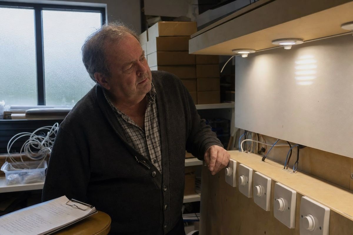
Antes de que cualquier controlador OEM salga de nuestra fábrica, lo probamos con una matriz de modelos de reguladores de intensidad más habituales en nuestros mercados de exportación: el Reino Unido, Alemania, Japón, Australia y otros países. Las normas relativas a los reguladores de intensidad varían según la región, por lo que un controlador ajustado para un mercado puede fallar en otro.
Elige un controlador comprobando cinco parámetros en relación con tus reguladores de intensidad: carga mínima, corriente de arranque, corriente de mantenimiento, rango de regulación y pruebas de compatibilidad documentadas. Una lista de compatibilidad publicada es mucho más importante que la simple palabra “regulable” que aparece en una ficha técnica.
Ver la indicación “regulable mediante TRIAC” en una ficha técnica no te dice prácticamente nada sobre su comportamiento en la práctica. En los proyectos de iluminación B2B, la siguiente lista de comprobación práctica es lo que marca la diferencia entre una puesta en marcha sin problemas y un almacén lleno de devoluciones.
La lista de comprobación de compatibilidad de cinco puntos
| Parámetro | Qué hay que comprobar | Por qué es importante |
|---|---|---|
| Requisito de carga mínima | La potencia total de las luminarias supera la carga mínima del regulador de intensidad. | Los LED individuales de baja potencia que están por debajo del umbral provocan parpadeos e inestabilidad |
| Corriente de arranque | El controlador limita el pico de corriente de encendido | Evita los disparos indeseados de los interruptores AFCI/GFCI y los daños en los reguladores de intensidad luminosa |
| Corriente de retención | El controlador mantiene la corriente suficiente para el TRIAC | Evita las caídas de tensión a mitad de ciclo y el parpadeo a niveles bajos de atenuación |
| Rango de atenuación | Rango mínimo especificado, por ejemplo, hasta 1% o 5% | Determina si realmente es posible lograr una regulación de la intensidad luminosa profunda y suave |
| Pruebas de compatibilidad | El proveedor publica una lista de reguladores de intensidad probados | Prueba del rendimiento real de la conexión, no solo una etiqueta de marketing |
Elige el controlador adecuado según el tipo de regulador de intensidad y el mercado
Confirma si el proyecto utiliza reguladores de intensidad de tipo «leading-edge», «trailing-edge» o mixtos. Si no se conoce la respuesta o se trata de un sistema mixto, especifica un controlador híbrido con detección automática. Comprueba también la tensión y la frecuencia de la red eléctrica del mercado de destino. La compatibilidad de los controladores LED varía según la región: un proyecto japonés de 100 V se comporta de forma diferente a uno alemán de 230 V, por lo que realizamos los ajustes necesarios durante la fase de desarrollo.
Saber cuándo el corte de fase no es la solución
Voy a plantear la objeción que a veces me plantean los compradores: ¿es la regulación por corte de fase realmente la opción adecuada? Para una adaptación de dos hilos con mandos de pared, sí: es sencillo, familiar y barato de instalar. Pero para proyectos que requieran una regulación precisa y profunda, escenas personalizables o una gestión de todo el edificio, los sistemas de 0-10 V o DALI pueden ser la mejor opción, ya que separan la señal de control del suministro de energía. Parte de un asesoramiento técnico honesto consiste en indicar al cliente cuándo le conviene más una arquitectura diferente. Cuando el corte de fase sea la opción adecuada, insiste en que te proporcionen muestras y pruébalas en tus propios reguladores antes de comprometerte a comprar en grandes cantidades.
Conclusión
La regulación por corte de fase sigue siendo la opción más utilizada en el control de la iluminación, pero su éxito depende ahora de la compatibilidad con los controladores LED. Comprueba la carga mínima, la corriente de mantenimiento, la corriente de arranque y el rango de regulación; a continuación, realiza una prueba antes de comprar.
Notas al pie
1. Wikipedia ofrece una descripción técnica detallada del control por disparo de fase y de las técnicas de modulación de onda sinusoidal. ↩︎
2. El IEEE es la principal autoridad en materia de normas de ingeniería eléctrica para conceptos como los ángulos de fase en los sistemas eléctricos. ↩︎
3. La ISO elabora normas internacionales sobre sistemas eléctricos y requisitos globales relativos a la tensión de red. ↩︎
4. Wikipedia ofrece información exhaustiva sobre la tecnología de los reguladores de intensidad y los factores que influyen en el rango de regulación. ↩︎
5. El NIST lleva a cabo investigaciones técnicas y elabora normas sobre fenómenos eléctricos, como los picos de corriente de arranque. ↩︎