














คำถามเกี่ยวกับการลดแสงแบบ Phase-cut เข้ามาในอินบ็อกซ์ของฉันเกือบทุกสัปดาห์ ผู้ซื้อบอกฉันว่าไดรเวอร์ LED แบบ “ลดแสงได้” ของพวกเขากระพริบ มีเสียงฮัม หรือเสียหายเมื่อใช้งานในระดับแสงต่ำ ความล้มเหลวนั้นทำให้โปรเจกต์สูญเสียเงินจริง หลังจากหลายปีในการผลิตไดรเวอร์ LED แบบลดแสงได้ที่โรงงานของเราในเซินเจิ้น ฉันต้องการอธิบายว่าเทคโนโลยีนี้ทำงานอย่างไรจริง ๆ — และจะทำให้มันทำงานเพื่อคุณได้อย่างไร.
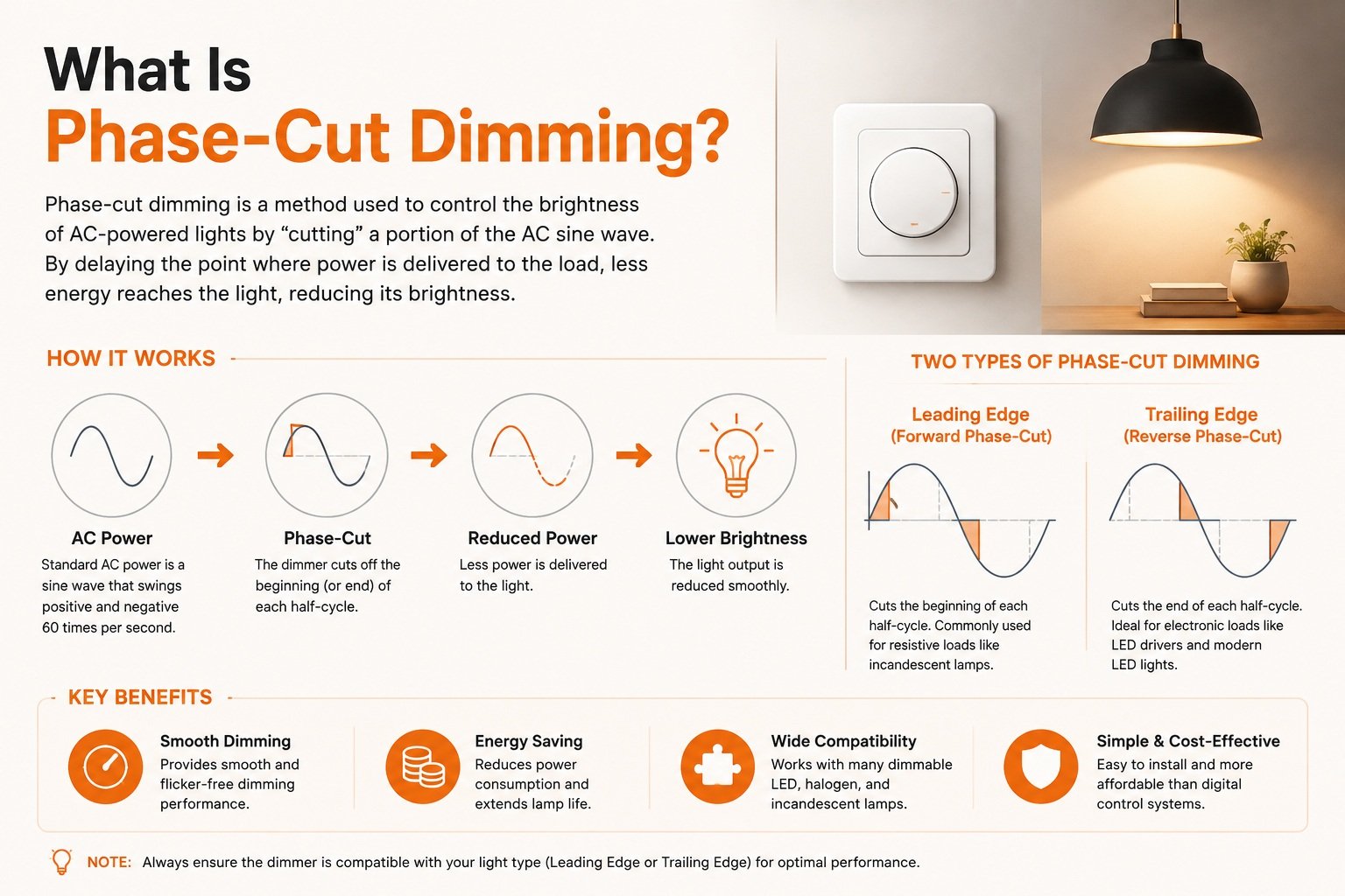
การลดแสงแบบ Phase-cut เป็นวิธีการควบคุมความสว่างของ LED โดยการตัดส่วนหนึ่งของรูปคลื่นแรงดันไฟฟ้ากระแสสลับก่อนที่จะถึงไดรเวอร์ LED ตัวลดแสงจะสลับคลื่นไซน์เปิดหรือปิดที่จุดที่กำหนดในแต่ละครึ่งรอบ ซึ่งจะลดกำลังไฟฟ้าที่ส่งถึงและทำให้แสงหรี่ลง.
คำตอบสั้น ๆ นั้นครอบคลุมคำจำกัดความ แต่เรื่องจริงอยู่ในรายละเอียด ให้ฉันอธิบายว่ามันทำงานอย่างไร ทำไมมันถึงล้มเหลว และวิธีเลือกฮาร์ดแวร์ที่เหมาะสม.
การลดแสงแบบ Phase-cut ทำงานอย่างไรในไดรเวอร์ LED จริง ๆ?
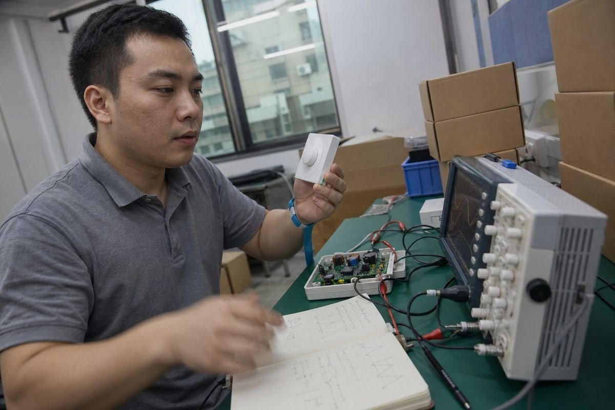
เมื่อวิศวกรของเราทดสอบการออกแบบไดรเวอร์ใหม่ สิ่งแรกที่พวกเขาวางบนโต๊ะทดสอบคือออสซิลโลสโคป การดูรูปคลื่นที่ถูกตัดบอกเราได้มากกว่าที่เอกสารข้อมูลใด ๆ จะอ้างได้.
ตัวลดแสงแบบ Phase-cut ตัดแต่ละครึ่งรอบของ AC โดยหน่วงหรือหยุดการนำไฟฟ้า ไดรเวอร์ LED อ่านรูปคลื่นที่สั้นลงนี้ วัดมุมเฟส และแปลงเป็นกระแสเอาต์พุตคงที่ที่ต่ำลงตามสัดส่วน ซึ่งช่วยลดความสว่างของ LED อย่างราบรื่นและปลอดภัย.

แหล่งจ่ายจากผนังเป็นคลื่นไซน์ AC ที่เรียบ ตัวลดแสงแบบ Phase-cut ไม่ได้ลดแรงดันไฟฟ้านั้นในลักษณะแอนะล็อกที่นุ่มนวล แต่จะทำการ มอดูเลตคลื่นไซน์ 1: มันสลับกระแสเปิดและปิดที่จุดที่แม่นยำในทุกครึ่งรอบ สองครั้งต่อรอบ mains ส่วนที่ถูกตัดออกอธิบายด้วย มุมเฟส 2. การตัดที่มากขึ้นหมายถึงพลังงานที่ไปถึงโหลดน้อยลง ดังนั้นแสงจึงหรี่ลง ในทางเทคนิค การตัดรูปคลื่นจะลดค่า Root Mean Square (RMS) รวมของแรงดันไฟฟ้าและกำลังไฟฟ้าที่ส่งถึงแหล่งกำเนิดแสง.
จากรูปคลื่นที่ถูกตัดไปจนถึงแสงที่คงที่
ไส้หลอดแบบอินแคนเดสเซนต์เพียงแค่สว่างน้อยลงเมื่อได้รับพลังงานน้อยลง ไดรเวอร์ LED มีงานที่ยากกว่า มันต้องรับอินพุตที่ขรุขระและถูกขัดจังหวะนั้น และยังคงผลิตกระแสคงที่ที่สะอาดทางด้านเอาต์พุต นี่คือกระบวนการในขั้นตอนง่าย ๆ:
- ตัวลดแสงตัดรูปคลื่น AC ที่มุมเฟสที่เลือก.
- ส่วนหน้าของไดรเวอร์ตรวจจับว่ารูปคลื่นถูกตัดออกไปเท่าใด.
- วงจรภายในแปลงมุมเฟสนั้นเป็นระดับการลดแสง.
- ขั้นตอนเอาต์พุตส่งกระแสที่ต่ำลงและคงที่ให้กับ LED.
- LED หรี่ลงโดยไม่มีการกระพริบที่มองเห็นได้ — หากทุกอย่างเข้ากันได้.
ขั้นตอนที่ 2 คือจุดที่ปัญหาส่วนใหญ่เริ่มต้น หากไดรเวอร์อ่านรูปคลื่นผิด คุณจะได้แสงที่ไม่เสถียร นั่นคือเหตุผลที่การออกแบบอินพุตของไดรเวอร์สำคัญพอ ๆ กับตัวลดแสงเอง.
ทำไมวิธีนี้ยังคงอยู่รอดในโปรเจกต์สมัยใหม่
การลดแสงแบบ Phase-cut ทำงานกับสายไฟสองเส้นที่มีอยู่ ไม่มีสายควบคุมแยกต่างหาก ซึ่งแตกต่างจากระบบ 0-10V หรือ DALI สำหรับโปรเจกต์ปรับปรุงในบ้าน โรงแรม และพื้นที่บริการ การติดตั้งมีต้นทุนต่ำกว่าและใช้สวิตช์ผนังที่คุ้นเคย เมื่อ Olivia ผู้จัดการฝ่ายจัดซื้อที่เราทำงานด้วยในสิงคโปร์ ระบุไดรเวอร์ดาวน์ไลท์สำหรับปรับปรุง ความเข้ากันได้กับสายสองเส้นมักเป็นข้อกำหนดแรกของเธอ — สายไฟอยู่ในผนังแล้ว.
ทำไมฉันถึงเห็นการกระพริบหรือเสียงฮัมเมื่อใช้ตัวลดแสงแบบ Phase-cut กับไดรเวอร์ LED?
ตัวแทนจำหน่ายในอิตาลีเคยส่งกล่องตัวลดแสงที่ลูกค้าของเขาคืนมาให้เรา ทุกตัวทำงานปกติ — ปัญหาคือไดรเวอร์ที่ไม่เข้ากันที่ถูกจับคู่กับมัน กล่องนั้นสอนบทเรียนที่ยั่งยืนแก่ทีมของเราเกี่ยวกับการทดสอบความเข้ากันได้.
การกระพริบและเสียงฮัมมักมาจากความไม่เข้ากันทางไฟฟ้าระหว่างตัวลดแสงและไดรเวอร์ LED สาเหตุทั่วไปรวมถึงกระแส holding ไม่เพียงพอสำหรับตัวลดแสง TRIAC ข้อกำหนดโหลดขั้นต่ำที่ไม่เป็นไปตาม สไปก์กระแส inrush และไดรเวอร์ที่อ่านรูปคลื่นที่ถูกตัดผิด.

ไดรเวอร์ที่ติดฉลาก “ลดแสง TRIAC ได้” ยังคงสามารถกระพริบ มีเสียงฮัม แสดง dead travel หรือปฏิเสธที่จะลดแสงต่ำกว่าระดับหนึ่ง ฉลากอธิบายความตั้งใจ ไม่ใช่ประสิทธิภาพที่รับประกัน ประสิทธิภาพจริงขึ้นอยู่กับการผสมผสานเฉพาะของประเภทตัวลดแสง การออกแบบไดรเวอร์ และโหลด LED กล่าวอีกนัยหนึ่ง “ลดแสงได้” ไม่ได้หมายความว่า “เข้ากันได้กับตัวลดแสง”
โหมดความล้มเหลวหลักและสาเหตุของพวกมัน
| อาการ | สาเหตุที่เป็นไปได้ | สิ่งที่เกิดขึ้นทางไฟฟ้า |
|---|---|---|
| การกระพริบที่มองเห็นได้ | กระแส holding ต่ำเกินไป | TRIAC หลุดกลางรอบเพราะไดรเวอร์ LED ดึงกระแสน้อยเกินไปที่จะรักษาการนำไฟฟ้า |
| เสียงฮัมที่ได้ยิน | ความเครียดจากกระแสไฟกระชากตอนเริ่มต้น | การเปิดสวิตช์ที่คมชัดของไดม์เมอร์แบบ leading-edge ทำให้ชิ้นส่วนภายในไดม์เมอร์หรือไดรเวอร์สั่นสะเทือน |
| เอฟเฟกต์การกระโดดสว่างทันที | การตรวจจับระดับต่ำที่แย่ | แสงกระโดดไปยังความสว่างที่สูงขึ้นทันทีแทนที่จะเริ่มจากความสว่างต่ำ |
| ช่วงการหมุนที่ไม่มีผล | ช่วงการปรับ ความสว่างที่แคบ 4 | การหมุนปุ่มบางส่วนไม่ทำให้เกิดการเปลี่ยนแปลงที่มองเห็นได้ |
| การกะพริบแบบสุ่ม | โหลดขั้นต่ำไม่เพียงพอ | LED กำลังไฟต่ำตัวเดียวไม่สามารถตอบสนองความต้องการกำลังไฟขั้นต่ำของไดม์เมอร์ได้ |
ปัญหาที่มองไม่เห็น
มีสองประเด็นที่ควรให้ความสนใจเป็นพิเศษเพราะง่ายต่อการมองข้ามในระหว่างการสาธิตอย่างรวดเร็ว ประการแรก การปรับแสงแบบ phase-cut สามารถเพิ่มค่า Stroboscopic Visibility Measure (SVM) ได้อย่างมีนัยสำคัญ แม้ว่าจะไม่เห็นการกะพริบอย่างชัดเจน แต่ก็อาจทำให้เกิดอาการปวดตาหรือ “ภาพซ้อน” ของวัตถุที่เคลื่อนไหวได้ เราวัดค่า SVM บนสายการผลิตของเราด้วยเหตุผลนี้พอดี — ประสิทธิภาพแบบไม่มีการกะพริบคือข้อกำหนด ไม่ใช่แค่สโลแกน.
ประการที่สอง กระแสไฟกระชากตอนเริ่มต้นที่จุดเริ่มต้นของแต่ละรอบการนำไฟฟ้าสามารถสูงถึง 50 เท่าของกระแสไฟฟ้าสถานะคงที่ กระแสไฟกระชากนี้มักทำให้เซอร์กิตเบรกเกอร์แบบ AFCI และ GFCI ที่ไวต่อการทำงานตัดวงจรโดยไม่จำเป็น หากลูกค้ารายงานว่าเบรกเกอร์ตัดแบบสุ่มบนวงจรที่ปรับแสงได้ สิ่งแรกที่เราตรวจสอบคือกระแสไฟกระชาก.
วิธีแก้ไขสมัยใหม่: วงจร bleeder แบบแอคทีฟ
ไดรเวอร์รุ่นเก่าใช้ตัวต้านทานแบบคงที่เพื่อรักษากระแสไฟฟ้าคงค้างของ TRIAC ซึ่งสิ้นเปลืองพลังงานเป็นความร้อนตลอดเวลา ไดรเวอร์ระดับสูงในปัจจุบันใช้วงจร bleeder แบบแอคทีฟที่ปรับความต้านทานภายในแบบไดนามิก โดยรักษากระแสไฟฟ้าคงค้างเฉพาะเมื่อจำเป็นเท่านั้น ซึ่งช่วยลดความร้อนที่สูญเปล่าและปรับปรุงประสิทธิภาพที่ระดับการปรับแสงต่ำ — เป็นคุณสมบัติที่เราสร้างไว้ในสายไดรเวอร์ระดับกลางถึงสูงของเรา.
ความแตกต่างระหว่างการลดแสงแบบ Phase-cut แบบ leading-edge และ trailing-edge คืออะไร?
ผู้เข้าชมงานที่บูธของเรามักถามเรื่องนี้ก่อนสิ่งอื่นใด เรามีแผนภาพรูปคลื่นสองแบบพิมพ์ไว้บนเคาน์เตอร์ เพราะความแตกต่างเห็นได้ชัดที่สุดเมื่อเปรียบเทียบเคียงข้างกัน.
การปรับแสงแบบ leading-edge ตัดจุดเริ่มต้นของแต่ละครึ่งรอบของไฟฟ้ากระแสสลับโดยใช้การสวิตช์แบบ TRIAC หรือ SCR เหมาะกับโหลดหลอดไส้แบบดั้งเดิม การปรับแสงแบบ trailing-edge ตัดจุดสิ้นสุดของครึ่งรอบโดยใช้ MOSFET หรือ IGBT และโดยทั่วไปทำงานได้ดีกว่ากับไดรเวอร์ LED แบบอิเล็กทรอนิกส์.

นี่คือการเปรียบเทียบเคียงข้างกันที่เราแบ่งปันกับผู้ซื้อ:
| ลักษณะเฉพาะ | Leading-edge (เฟสไปข้างหน้า) | Trailing-edge (เฟสย้อนกลับ) |
|---|---|---|
| ส่วนของรูปคลื่นที่ถูกตัด | จุดเริ่มต้นของแต่ละครึ่งรอบ | ปลายของแต่ละครึ่งรอบ |
| ชิ้นส่วนสวิตช์ | TRIAC หรือ SCR | MOSFET หรือ IGBT |
| ชื่อเรียกอื่น | การหรี่แสงแบบ TRIAC | การปรับแสงแบบ ELV |
| ประเภทโหลดเดิม | หลอดไส้ หลอดฮาโลเจน | หม้อแปลงอิเล็กทรอนิกส์ ไดรเวอร์ LED |
| พฤติกรรมการเปิดสวิตช์ | การเปลี่ยนแปลงแรงดันไฟฟ้าอย่างกะทันหัน กระแสไฟกระชากสูง | การเปลี่ยนผ่านที่นุ่มนวลและค่อยเป็นค่อยไป |
| แนวโน้มเสียงรบกวน | มีแนวโน้มที่จะเกิดเสียงฮัมมากกว่า | การทำงานที่เงียบกว่า |
| การปรับแสงระดับต่ำ | มักมีข้อจำกัด | โดยทั่วไปนุ่มนวลกว่า |
| ฐานการติดตั้งที่มีอยู่ | ใหญ่มาก เป็นแบบดั้งเดิม | กำลังเติบโต เน้น LED |
ทำไมจุดตัดจึงสำคัญมาก
การควบคุมเฟสแบบไปข้างหน้าตัดแรงดันไฟฟ้าอย่างฉับพลันในช่วงกลางของรอบ การเปลี่ยนแปลงอย่างกะทันหันนี้กระทบส่วนหน้าของไดรเวอร์ LED แบบ capacitive อย่างรุนแรง ทำให้เกิดกระแสไฟกระชากและแนวโน้มเสียงฮัมตามที่อธิบายไว้ก่อนหน้านี้ นอกจากนี้ยังต้องการให้ไดรเวอร์จ่ายกระแสไฟฟ้าคงค้างเพียงพอ มิฉะนั้นไดม์เมอร์ TRIAC จะหลุดและไฟกะพริบ.
การควบคุมเฟสแบบย้อนกลับทำตรงกันข้าม แรงดันไฟฟ้าเพิ่มขึ้นตามธรรมชาติกับคลื่นไซน์ จากนั้นตัดออกก่อนที่ครึ่งรอบจะสิ้นสุด การเปิดสวิตช์แบบค่อยเป็นค่อยไปนี้เหมาะกับลักษณะ capacitive ของไดรเวอร์ LED แบบอิเล็กทรอนิกส์ ซึ่งเป็นเหตุผลว่าทำไมการปรับแสงแบบ ELV โดยทั่วไปจึงให้การทำงานที่เงียบกว่าและการปรับแสงระดับต่ำที่นุ่มนวลกว่ากับระบบที่เข้ากันได้.
ผู้ซื้อควรระบุแบบไหน?
ไม่มีผู้ชนะที่เป็นสากล การปรับแสงแบบ leading-edge ชนะในด้านฐานการติดตั้งที่มีอยู่ — ไดม์เมอร์ TRIAC หลายล้านตัวติดตั้งอยู่บนผนังทั่วโลกแล้ว ดังนั้นไดรเวอร์สำหรับการติดตั้งทดแทนต้องรองรับได้ การปรับแสงแบบ trailing-edge ชนะในด้านประสิทธิภาพของ LED คำตอบของเราเองมักเป็น “ทั้งสองแบบ”: เราพัฒนาไดรเวอร์แบบไฮบริดที่ตรวจจับประเภทไดม์เมอร์อัตโนมัติ เพราะลูกค้าปลายทางของผู้จัดจำหน่ายมักไม่รู้ว่าไดม์เมอร์ตัวใดติดตั้งอยู่บนผนัง ส่วนขยายที่น่าสนใจ: ระบบปรับแสงแบบ dim-to-warm ขั้นสูงใช้มุมเฟสเฉพาะของรูปคลื่นที่ถูกตัดเป็นตัวกระตุ้นข้อมูล เพื่อเปลี่ยนอุณหภูมิสีให้เลียนแบบการเลื่อนสีเหลืองอำพันของไส้หลอดแบบดั้งเดิม.
ฉันจะเลือกไดรเวอร์ LED ที่เหมาะสมเพื่อให้เข้ากันได้กับตัวลดแสงแบบ Phase-cut ได้อย่างไร?
ก่อนที่ไดรเวอร์ OEM ใดๆ จะออกจากโรงงานของเรา เราทดสอบกับเมทริกซ์ของรุ่นไดม์เมอร์ยอดนิยมจากตลาดส่งออกของเรา — สหราชอาณาจักร เยอรมนี ญี่ปุ่น ออสเตรเลีย และอื่นๆ มาตรฐานไดม์เมอร์แตกต่างกันตามภูมิภาค ดังนั้นไดรเวอร์ที่ปรับแต่งสำหรับตลาดหนึ่งอาจทำงานสะดุดในอีกตลาดหนึ่ง.
เลือกไดรเวอร์โดยตรวจสอบพารามิเตอร์ห้าตัวกับไดม์เมอร์เป้าหมายของคุณ: โหลดขั้นต่ำ กระแสไฟกระชาก กระแสไฟฟ้าคงค้าง ช่วงการปรับแสง และการทดสอบความเข้ากันได้ที่บันทึกไว้ รายการความเข้ากันได้ที่เผยแพร่มีความสำคัญมากกว่าคำว่า “dimmable” เพียงคำเดียวบนเอกสารข้อมูล.
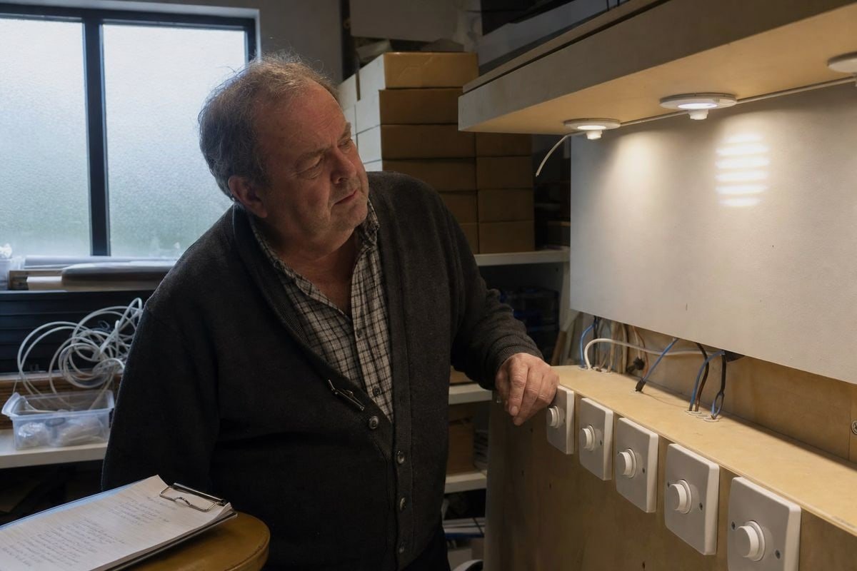
การเห็นคำว่า “TRIAC dimmable” พิมพ์บนเอกสารข้อมูลแทบไม่ได้บอกอะไรเกี่ยวกับพฤติกรรมในโลกจริงเลย สำหรับโครงการไฟส่องสว่างแบบ B2B รายการตรวจสอบเชิงปฏิบัติด้านล่างคือสิ่งที่แยกการเปิดตัวที่ราบรื่นออกจากคลังสินค้าที่เต็มไปด้วยสินค้าคืน.
รายการตรวจสอบความเข้ากันได้ห้าจุด
| พารามิเตอร์ | สิ่งที่ต้องตรวจสอบ | เหตุใดจึงสำคัญ |
|---|---|---|
| ข้อกำหนดโหลดขั้นต่ำ | กำลังไฟรวมของโคมไฟเกินโหลดขั้นต่ำของตัวหรี่ไฟ | LED กำลังต่ำเดี่ยวที่ต่ำกว่าเกณฑ์ทำให้เกิดการกระพริบและความไม่เสถียร |
| กระแสไฟกระชากตอนเปิดเครื่อง (Inrush current) | ไดรเวอร์จำกัดการพุ่งสูงของกระแสตอนเปิดเครื่อง | ป้องกันการตัดวงจรที่รบกวนของเบรกเกอร์ AFCI/GFCI และความเสียหายของตัวหรี่ไฟ |
| กระแสคงค้าง (Holding current) | ไดรเวอร์รักษากระแสให้เพียงพอสำหรับ TRIAC | หยุดการขาดตอนกลางรอบและอาการกระพริบที่ระดับความสว่างต่ำ |
| ช่วงการหรี่แสง | ค่าต่ำสุดที่ระบุ เช่น ลดลงถึง 1% หรือ 5% | กำหนดว่าการหรี่แสงที่ลึกและนุ่มนวลทำได้จริงหรือไม่ |
| การทดสอบความเข้ากันได้ | ผู้จำหน่ายเผยแพร่รายการตัวหรี่ไฟที่ผ่านการทดสอบ | หลักฐานของประสิทธิภาพการจับคู่จริง ไม่ใช่เพียงฉลากทางการตลาด |
จับคู่ไดรเวอร์กับประเภทตัวลดแสง — และตลาด
ยืนยันว่าโครงการใช้ตัวหรี่ไฟแบบ leading-edge, trailing-edge หรือแบบผสม หากไม่ทราบหรือเป็นแบบผสม ให้ระบุ ไดรเวอร์แบบไฮบริดพร้อมระบบตรวจจับอัตโนมัติ. นอกจากนี้ ให้ยืนยันแรงดันไฟฟ้าหลักและความถี่ของตลาดปลายทาง ความเข้ากันได้ของ LED ไดรเวอร์ขึ้นอยู่กับภูมิภาค: โครงการ 100V ในญี่ปุ่นมีพฤติกรรมแตกต่างจากโครงการ 230V ในเยอรมนี และเราปรับเทียบตามนั้นระหว่างการพัฒนา.
รู้ว่าเมื่อใดที่ Phase-cut ไม่ใช่คำตอบ
ฉันจะยกข้อโต้แย้งที่ผู้ซื้อมักยกขึ้นกับฉัน: การหรี่แสงแบบตัดเฟสเป็นตัวเลือกที่ถูกต้องหรือไม่? สำหรับการติดตั้งแบบสองสายพร้อมสวิตช์ติดผนัง ใช่ — มันเรียบง่าย คุ้นเคย และติดตั้งถูก แต่สำหรับโครงการที่ต้องการการหรี่แสงลึกที่แม่นยำ ฉากปรับแสงได้ หรือการจัดการทั่วทั้งอาคาร 0-10V หรือ DALI อาจเหมาะสมกว่า เพราะแยกสัญญาณควบคุมจากการจ่ายไฟ การสนับสนุนทางเทคนิคที่ซื่อสัตย์ส่วนหนึ่งคือการบอกลูกค้าเมื่อสถาปัตยกรรมอื่นจะให้บริการพวกเขาได้ดีกว่า เมื่อการตัดเฟสเหมาะสม ควรยืนยันให้ได้ตัวอย่างและทดสอบกับตัวหรี่ไฟจริงก่อนสั่งซื้อปริมาณมาก.
บทสรุป
การหรี่แสงแบบตัดเฟสยังคงเป็นหัวใจหลักของการควบคุมแสง แต่ความสำเร็จของมันตอนนี้ขึ้นอยู่กับความเข้ากันได้ของ LED ไดรเวอร์ ตรวจสอบโหลดขั้นต่ำ กระแสคงค้าง กระแสไฟกระชาก และช่วงการหรี่แสง — จากนั้นทดสอบก่อนซื้อ.
เชิงอรรถ
Wikipedia ให้ภาพรวมทางเทคนิคโดยละเอียดเกี่ยวกับเทคนิค phase-fired control และการมอดูเลตคลื่นไซน์. ↩︎
IEEE เป็นหน่วยงานชั้นนำด้านมาตรฐานวิศวกรรมไฟฟ้าสำหรับแนวคิดเช่นมุมเฟสในระบบไฟฟ้ากำลัง. ↩︎
ISO พัฒนามาตรฐานระหว่างประเทศสำหรับระบบไฟฟ้าและข้อกำหนดแรงดันไฟฟ้าหลักทั่วโลก. ↩︎
Wikipedia ให้ข้อมูลครอบคลุมเกี่ยวกับเทคโนโลยีตัวหรี่ไฟและปัจจัยที่ส่งผลต่อช่วงการหรี่แสง. ↩︎
NIST ให้การวิจัยทางเทคนิคและมาตรฐานเกี่ยวกับปรากฏการณ์ทางไฟฟ้าเช่นการพุ่งของกระแสไฟกระชาก. ↩︎