














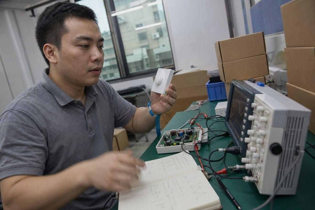
Các câu hỏi về điều chỉnh độ sáng cắt pha (phase-cut dimming) gần như xuất hiện trong hộp thư của tôi mỗi tuần. Người mua cho tôi biết bộ điều khiển LED “có thể điều chỉnh độ sáng” của họ nhấp nháy, kêu ù, hoặc hỏng ở mức sáng thấp. Sự cố đó khiến các dự án tốn kém thực sự. Sau nhiều năm sản xuất bộ điều khiển LED có thể điều chỉnh độ sáng tại cơ sở của chúng tôi ở Thâm Quyến, tôi muốn giải thích công nghệ này thực sự hoạt động như thế nào — và làm thế nào để nó hoạt động hiệu quả cho bạn.
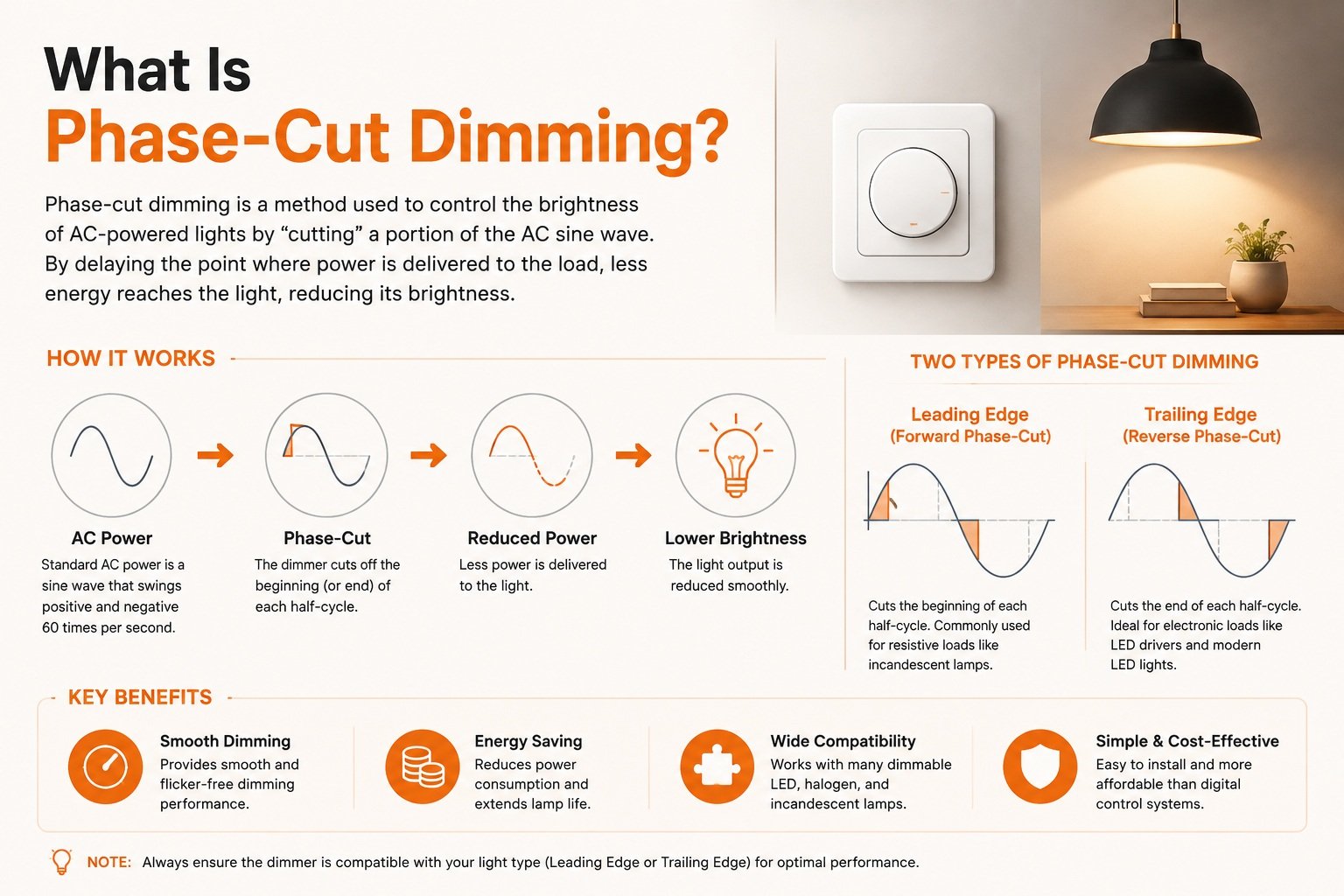
Điều chỉnh độ sáng cắt pha là một phương pháp kiểm soát độ sáng LED bằng cách cắt bỏ một phần dạng sóng điện áp xoay chiều (AC) trước khi nó đến bộ điều khiển LED. Bộ điều chỉnh độ sáng bật/tắt sóng sin tại một điểm đã định trong mỗi nửa chu kỳ, giảm công suất truyền tải và làm mờ đèn.
Câu trả lời ngắn gọn đó bao quát định nghĩa. Nhưng câu chuyện thực sự nằm ở chi tiết. Hãy để tôi hướng dẫn bạn cách nó hoạt động, tại sao nó hỏng, và cách chọn phần cứng phù hợp.
Điều chỉnh độ sáng cắt pha thực sự hoạt động như thế nào trong bộ điều khiển LED?
Khi các kỹ sư của chúng tôi kiểm tra một thiết kế bộ điều khiển mới, điều đầu tiên họ đặt lên bàn thử nghiệm là máy hiện sóng (oscilloscope). Quan sát dạng sóng bị cắt cho chúng tôi biết nhiều hơn bất kỳ tuyên bố nào trên bảng dữ liệu.
Bộ điều chỉnh độ sáng cắt pha cắt mỗi nửa chu kỳ AC, trì hoãn hoặc kết thúc dẫn điện. Bộ điều khiển LED đọc dạng sóng bị rút ngắn này, đo góc pha, và chuyển đổi nó thành dòng điện đầu ra không đổi thấp hơn tương ứng, giúp giảm độ sáng LED một cách mượt mà và an toàn.

Nguồn điện tường là một sóng sin AC mượt mà. Bộ điều chỉnh độ sáng cắt pha không hạ điện áp đó một cách nhẹ nhàng, tương tự. Thay vào đó, nó thực hiện một loại điều chế sóng sin 1: nó bật/tắt dòng điện tại một điểm chính xác trong mỗi nửa chu kỳ, hai lần mỗi chu kỳ nguồn. Phần bị loại bỏ được mô tả bằng góc pha 2. Cắt nhiều hơn có nghĩa là ít năng lượng đến tải hơn, vì vậy đèn mờ đi. Về mặt kỹ thuật, việc cắt dạng sóng làm giảm tổng điện áp Root Mean Square (RMS) và công suất truyền đến nguồn sáng.
Từ dạng sóng bị cắt đến ánh sáng ổn định
Một dây tóc đèn sợi đốt chỉ đơn giản là phát sáng yếu hơn khi nhận ít công suất hơn. Bộ điều khiển LED có công việc khó khăn hơn. Nó phải nhận đầu vào gồ ghề, bị gián đoạn đó và vẫn tạo ra dòng điện không đổi, sạch ở phía đầu ra. Đây là quy trình theo các bước đơn giản:
- Bộ điều chỉnh độ sáng cắt dạng sóng AC tại một góc pha đã chọn.
- Phần đầu của bộ điều khiển phát hiện bao nhiêu phần dạng sóng đã bị loại bỏ.
- Mạch nội bộ chuyển đổi góc pha đó thành mức điều chỉnh độ sáng.
- Tầng đầu ra cung cấp dòng điện thấp hơn, ổn định cho đèn LED.
- Đèn LED mờ đi mà không có nhấp nháy nhìn thấy — nếu mọi thứ tương thích.
Bước 2 là nơi hầu hết các vấn đề bắt đầu. Nếu bộ điều khiển đọc sai dạng sóng, bạn sẽ có ánh sáng không ổn định. Đó là lý do tại sao thiết kế đầu vào của bộ điều khiển quan trọng như chính bộ điều chỉnh độ sáng.
Tại sao phương pháp này vẫn tồn tại trong các dự án hiện đại
Điều chỉnh độ sáng cắt pha hoạt động trên hệ thống dây hai dây hiện có. Không có cáp điều khiển riêng, không giống như hệ thống 0-10V hoặc DALI Đối với các dự án cải tạo trong nhà ở, khách sạn, và không gian dịch vụ, điều đó có nghĩa là chi phí lắp đặt thấp hơn và các công tắc tường quen thuộc. Khi Olivia, một quản lý mua hàng chúng tôi hợp tác tại Singapore, chỉ định bộ điều khiển đèn downlight cải tạo, tương thích hai dây thường là yêu cầu đầu tiên của cô ấy — hệ thống dây đã có sẵn trong tường.
Tại sao tôi thấy nhấp nháy hoặc kêu ù khi sử dụng bộ điều chỉnh độ sáng cắt pha với bộ điều khiển LED?
Một nhà phân phối ở Ý từng gửi cho chúng tôi một hộp bộ điều chỉnh độ sáng mà khách hàng của họ đã trả lại. Mỗi cái đều hoạt động tốt — vấn đề là các bộ điều khiển không khớp mà chúng được ghép cùng. Hộp đó đã dạy cho đội ngũ của chúng tôi một bài học lâu dài về kiểm tra tương thích.
Nhấp nháy và kêu ù thường đến từ sự không tương thích điện giữa bộ điều chỉnh độ sáng và bộ điều khiển LED. Các nguyên nhân phổ biến bao gồm dòng điện giữ (holding current) không đủ cho bộ điều chỉnh độ sáng TRIAC, yêu cầu tải tối thiểu không được đáp ứng, xung dòng khởi động (inrush current), và bộ điều khiển đọc sai dạng sóng bị cắt.

Một bộ điều khiển được gắn nhãn “TRIAC dimmable” vẫn có thể nhấp nháy, kêu ù, có vùng chết (dead travel), hoặc từ chối mờ xuống dưới một mức nhất định. Nhãn mô tả ý định, không phải hiệu suất đảm bảo. Hiệu suất thực tế phụ thuộc vào sự kết hợp cụ thể của loại bộ điều chỉnh độ sáng, thiết kế bộ điều khiển, và tải LED. Nói cách khác, “có thể điều chỉnh độ sáng” không có nghĩa là “tương thích với bộ điều chỉnh độ sáng.”
Các chế độ hỏng chính và nguyên nhân của chúng
| Triệu chứng | Nguyên nhân có khả năng | Điều gì đang xảy ra về mặt điện |
|---|---|---|
| Nhấp nháy nhìn thấy | Dòng điện giữ quá thấp | TRIAC ngắt giữa chu kỳ vì bộ điều khiển LED tiêu thụ quá ít dòng điện để giữ nó dẫn điện |
| Kêu ù nghe được | Ứng suất dòng điện xung kích | Sự bật nhanh của bộ điều chỉnh độ sáng leading-edge làm rung các linh kiện trong bộ điều chỉnh hoặc driver |
| Hiệu ứng bật sáng đột ngột | Phát hiện mức thấp kém | Đèn nhảy đột ngột lên độ sáng cao hơn thay vì khởi động mờ |
| Khoảng chết | Hẹp Dải điều chỉnh độ sáng 4 | Một phần vòng xoay núm không tạo ra thay đổi nhìn thấy được |
| Nhấp nháy ngẫu nhiên | Không đáp ứng tải tối thiểu | Một đèn LED công suất thấp đơn lẻ không thể đáp ứng yêu cầu công suất tối thiểu của bộ điều chỉnh độ sáng |
Các vấn đề vô hình
Hai vấn đề đáng được quan tâm đặc biệt vì chúng dễ bị bỏ sót trong buổi demo nhanh. Thứ nhất, điều chỉnh độ sáng cắt pha có thể làm tăng đáng kể Chỉ số Đo Độ Nhấp Nháy (SVM). Ngay cả khi hiện tượng nhấp nháy không nhìn thấy một cách có ý thức, nó có thể gây mỏi mắt hoặc “bóng ma” của các vật thể chuyển động. Chúng tôi đo SVM trên dây chuyền sản xuất của mình chính vì lý do này — hiệu suất không nhấp nháy là một thông số kỹ thuật, không phải là khẩu hiệu.
Thứ hai, xung dòng điện khởi động tại thời điểm bắt đầu mỗi chu kỳ dẫn điện có thể đạt tới 50 lần dòng điện ổn định. Xung này thường gây ra hiện tượng ngắt mạch phiền toái của các bộ ngắt AFCI và GFBI nhạy cảm. Nếu khách hàng báo cáo hiện tượng ngắt mạch ngẫu nhiên trên mạch điều chỉnh độ sáng, dòng điện xung kích là điều đầu tiên chúng tôi kiểm tra.
Giải pháp hiện đại: mạch bleeder chủ động
Các driver cũ sử dụng điện trở xả cố định để duy trì dòng điện giữ của TRIAC, lãng phí năng lượng dưới dạng nhiệt liên tục. Các driver cao cấp hiện nay sử dụng mạch xả chủ động điều chỉnh điện trở nội bộ một cách linh hoạt, chỉ duy trì dòng điện giữ khi cần thiết. Điều này cắt giảm nhiệt lãng phí và cải thiện hiệu suất ở mức điều chỉnh độ sáng thấp — một tính năng chúng tôi tích hợp vào các dòng driver tầm trung và cao cấp.
Sự khác biệt giữa điều chỉnh độ sáng cắt pha biên dẫn đầu (leading-edge) và biên dẫn sau (trailing-edge) là gì?
Khách tham quan hội chợ thương mại tại gian hàng của chúng tôi thường hỏi điều này trước tiên. Chúng tôi giữ hai biểu đồ dạng sóng in trên quầy, vì sự khác biệt dễ nhìn thấy nhất khi đặt cạnh nhau.
Điều chỉnh độ sáng leading-edge cắt phần đầu của mỗi nửa chu kỳ AC bằng cách sử dụng chuyển mạch TRIAC hoặc SCR, phù hợp với tải đèn sợi đốt truyền thống. Điều chỉnh độ sáng trailing-edge cắt phần cuối của nửa chu kỳ bằng MOSFET hoặc IGBT, và thường hoạt động tốt hơn với driver LED điện tử.

Đây là so sánh cạnh nhau chúng tôi chia sẻ với người mua:
| Tính năng | Cạnh trước (pha thuận) | Cạnh sau (pha ngược) |
|---|---|---|
| Phần dạng sóng bị cắt | Phần đầu của mỗi nửa chu kỳ | Cuối mỗi nửa chu kỳ |
| Linh kiện chuyển mạch | TRIAC hoặc SCR | MOSFET hoặc IGBT |
| Còn được gọi là | Điều chỉnh độ sáng TRIAC | Điều chỉnh độ sáng ELV |
| Loại tải ban đầu | Đèn sợi đốt, halogen | Biến áp điện tử, driver LED |
| Hành vi bật | Bước điện áp đột ngột, dòng xung kích cao | Chuyển tiếp dần dần, mượt mà hơn |
| Xu hướng nhiễu | Dễ bị ù hơn | Hoạt động êm hơn |
| Điều chỉnh độ sáng mức thấp | Thường bị hạn chế | Nhìn chung mượt mà hơn |
| Cơ sở lắp đặt hiện có | Rất lớn, truyền thống | Đang phát triển, tập trung vào LED |
Tại sao điểm cắt lại quan trọng đến vậy
Điều khiển pha thuận bật điện áp đột ngột giữa chu kỳ. Bước đột ngột đó tác động mạnh vào phần đầu tụ điện của driver LED, tạo ra xung dòng điện khởi động và xu hướng ù như đã mô tả trước đó. Nó cũng yêu cầu driver cung cấp đủ dòng điện giữ, nếu không bộ điều chỉnh độ sáng TRIAC sẽ ngắt và đèn nhấp nháy.
Điều khiển pha ngược làm điều ngược lại. Điện áp tăng tự nhiên theo sóng sin, sau đó tắt trước khi nửa chu kỳ kết thúc. Sự bật dần dần này phù hợp với bản chất tụ điện của driver LED điện tử, đó là lý do tại sao điều chỉnh độ sáng ELV thường mang lại hoạt động êm hơn và điều chỉnh độ sáng mức thấp mượt mà hơn với các hệ thống tương thích.
Người mua nên chỉ định loại nào?
Không có bên thắng tuyệt đối. Điều chỉnh độ sáng leading-edge thắng về cơ sở lắp đặt — hàng triệu bộ điều chỉnh độ sáng TRIAC đã được lắp trên tường trên toàn thế giới, vì vậy driver cải tạo phải xử lý được. Điều chỉnh độ sáng trailing-edge thắng về hiệu suất LED. Câu trả lời của chúng tôi thường là “cả hai”: chúng tôi phát triển driver lai tự động phát hiện loại bộ điều chỉnh độ sáng, vì khách hàng cuối của nhà phân phối hiếm khi biết bộ điều chỉnh độ sáng nào đang trên tường. Một mở rộng thú vị: các hệ thống dim-to-warm tiên tiến sử dụng góc pha cụ thể của dạng sóng cắt làm tín hiệu dữ liệu, chuyển đổi nhiệt độ màu để mô phỏng sự trôi màu hổ phách của dây tóc truyền thống.
Làm thế nào để tôi chọn bộ điều khiển LED phù hợp để đảm bảo tương thích với bộ điều chỉnh độ sáng cắt pha?
Trước khi bất kỳ driver OEM nào rời khỏi nhà máy của chúng tôi, chúng tôi chạy thử nó với một ma trận các mẫu bộ điều chỉnh độ sáng phổ biến từ các thị trường xuất khẩu của chúng tôi — Anh, Đức, Nhật Bản, Úc và hơn thế nữa. Tiêu chuẩn bộ điều chỉnh độ sáng khác nhau theo khu vực, vì vậy một driver được tinh chỉnh cho một thị trường có thể gặp trục trặc ở thị trường khác.
Chọn driver bằng cách xác minh năm thông số so với bộ điều chỉnh độ sáng mục tiêu: tải tối thiểu, dòng điện xung kích, dòng điện giữ, dải điều chỉnh độ sáng và kiểm tra tương thích được ghi nhận. Danh sách tương thích được công bố quan trọng hơn nhiều so với từ “dimmable” đơn lẻ trên bảng dữ liệu.
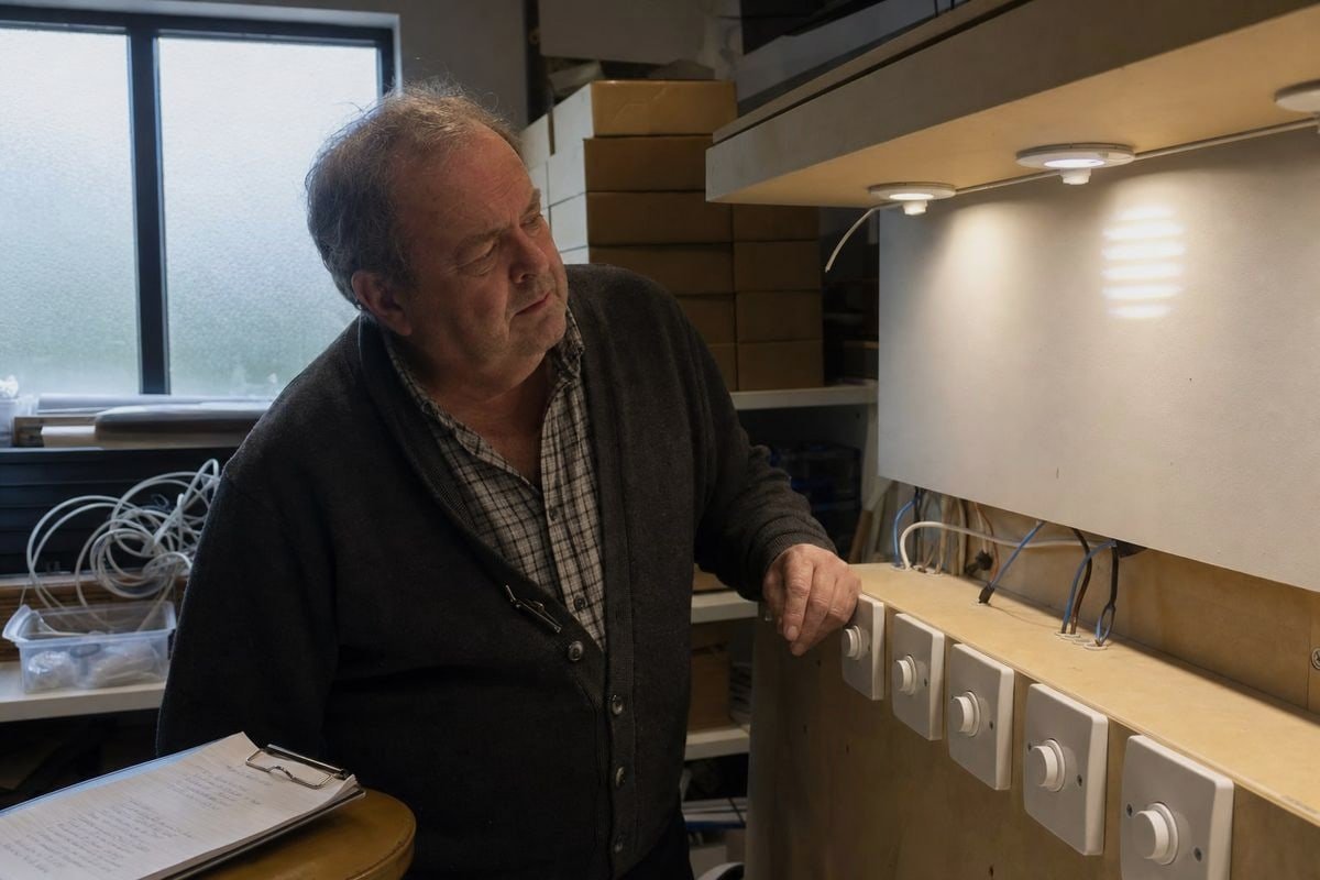
Nhìn thấy “TRIAC dimmable” in trên bảng thông số kỹ thuật hầu như không cho bạn biết gì về hành vi thực tế. Đối với các dự án chiếu sáng B2B, danh sách kiểm tra thực tế dưới đây là điều phân biệt giữa triển khai suôn sẻ và một kho đầy hàng trả lại.
Danh sách kiểm tra tương thích năm điểm
| Tham số | Điều cần xác minh | Lý do quan trọng |
|---|---|---|
| Yêu cầu tải tối thiểu | Tổng công suất thiết bị chiếu sáng vượt quá tải tối thiểu của bộ điều chỉnh độ sáng | Đèn LED công suất thấp đơn lẻ dưới ngưỡng gây nhấp nháy và mất ổn định |
| Dòng điện xung kích | Driver giới hạn xung dòng khởi động | Ngăn ngừa sự cố ngắt rác của bộ ngắt AFCI/GFCI và hư hỏng bộ điều chỉnh độ sáng |
| Dòng giữ | Driver duy trì đủ dòng cho TRIAC | Ngăn chặn sụt áp giữa chu kỳ và nhấp nháy ở mức độ sáng thấp |
| Phạm vi làm mờ | Điểm cuối thấp được chỉ định, ví dụ: xuống đến 1% hoặc 5% | Xác định liệu độ mờ sâu, mượt mà có thực sự đạt được hay không |
| Kiểm tra tương thích | Nhà cung cấp công bố danh sách bộ điều chỉnh độ sáng đã được kiểm tra | Bằng chứng về hiệu suất ghép nối thực tế, không chỉ là nhãn tiếp thị |
Khớp bộ điều khiển với loại bộ điều chỉnh độ sáng — và thị trường
Xác nhận dự án sử dụng bộ điều chỉnh độ sáng cạnh dẫn, cạnh trễ hay hỗn hợp. Nếu câu trả lời không rõ hoặc hỗn hợp, chỉ định một driver lai với tính năng tự động phát hiện. Cũng xác nhận điện áp nguồn và tần số của thị trường đích. Khả năng tương thích của driver LED mang tính khu vực: dự án 100V tại Nhật Bản hoạt động khác với dự án 230V tại Đức, và chúng tôi hiệu chỉnh tương ứng trong quá trình phát triển.
Biết khi nào cắt pha không phải là giải pháp
Tôi sẽ nêu ra ý kiến phản đối mà người mua đôi khi đưa ra với tôi: liệu điều chỉnh độ sáng cắt pha có phải là lựa chọn đúng đắn không? Đối với dự án cải tạo hai dây với công tắc treo tường, câu trả lời là có — đơn giản, quen thuộc và chi phí lắp đặt thấp. Nhưng đối với các dự án cần độ mờ sâu chính xác, cảnh điều chỉnh hoặc quản lý toàn tòa nhà, 0-10V hoặc DALI có thể phù hợp hơn, vì chúng tách biệt tín hiệu điều khiển khỏi nguồn điện. Một phần của hỗ trợ kỹ thuật trung thực là cho khách hàng biết khi nào một kiến trúc khác sẽ phục vụ họ tốt hơn. Khi cắt pha là lựa chọn phù hợp, hãy yêu cầu mẫu và chạy thử trên bộ điều chỉnh độ sáng thực tế của bạn trước khi cam kết số lượng lớn.
Sự kết luận
Điều chỉnh độ sáng cắt pha vẫn là công cụ chính của điều khiển chiếu sáng, nhưng sự thành công của nó hiện phụ thuộc vào khả năng tương thích của driver LED. Xác minh tải tối thiểu, dòng giữ, dòng xung khởi động và phạm vi điều chỉnh độ sáng — sau đó kiểm tra trước khi mua.
Chú thích
Wikipedia cung cấp tổng quan kỹ thuật chi tiết về kỹ thuật điều khiển pha và điều chế sóng sin. ↩︎
IEEE là cơ quan hàng đầu về tiêu chuẩn kỹ thuật điện cho các khái niệm như góc pha trong hệ thống điện. ↩︎
ISO phát triển các tiêu chuẩn quốc tế cho hệ thống điện và yêu cầu điện áp nguồn toàn cầu. ↩︎
Wikipedia cung cấp thông tin toàn diện về công nghệ bộ điều chỉnh độ sáng và các yếu tố ảnh hưởng đến phạm vi điều chỉnh độ sáng. ↩︎
NIST cung cấp nghiên cứu kỹ thuật và tiêu chuẩn về các hiện tượng điện như xung dòng khởi động. ↩︎