














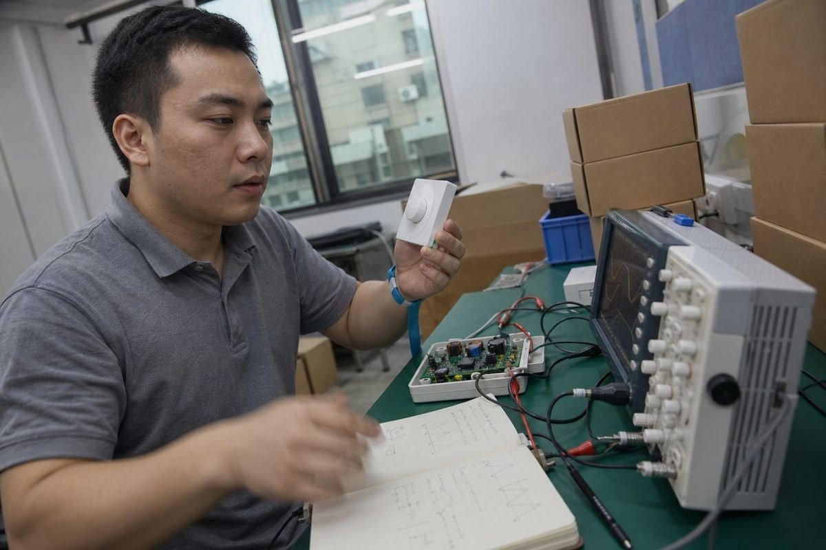
Je reçois presque chaque semaine dans ma boîte mail des questions concernant la gradation par coupure de phase. Les acheteurs me signalent que leurs drivers LED “ gradables ” clignotent, émettent un bourdonnement ou cessent de fonctionner à faible intensité. Ces défaillances coûtent cher aux projets. Après des années passées à fabriquer des drivers LED gradables dans notre usine de Shenzhen, je souhaite vous expliquer comment cette technologie fonctionne réellement — et comment en tirer le meilleur parti.
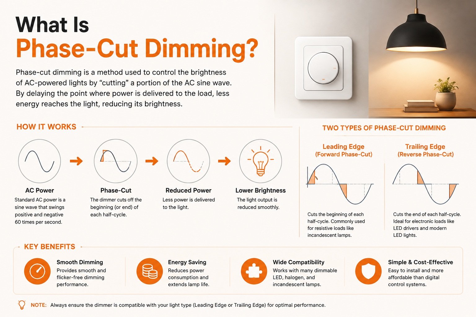
La gradation par coupure de phase est une méthode permettant de contrôler la luminosité d'une LED en coupant une partie de l'onde de tension alternative avant qu'elle n'atteigne le driver de la LED. Le variateur active ou désactive l'onde sinusoïdale à un point défini de chaque demi-cycle, ce qui réduit la puissance fournie et atténue la luminosité.
Cette réponse succincte résume la définition. Mais c'est dans les détails que réside toute l'histoire. Laissez-moi vous expliquer comment cela fonctionne, pourquoi cela peut échouer et comment choisir le matériel adapté.
Comment fonctionne concrètement la gradation par coupure de phase dans un alimentateur LED ?
Lorsque nos ingénieurs testent un nouveau modèle de haut-parleur, la première chose qu’ils installent sur le banc d’essai est un oscilloscope. L’observation de la forme d’onde saccadée nous en apprend davantage que n’importe quelle affirmation figurant dans une fiche technique.
Un variateur à coupure de phase interrompt chaque demi-cycle du courant alternatif, retardant ou mettant fin à la conduction. Le driver LED analyse cette forme d'onde raccourcie, mesure l'angle de phase et le convertit en un courant de sortie constant proportionnellement plus faible, ce qui réduit la luminosité de la LED de manière progressive et sûre.

Le courant secteur est une onde sinusoïdale alternative régulière. Un variateur à coupure de phase ne réduit pas cette tension de manière progressive et analogique. Au contraire, il effectue une sorte de modulation sinusoïdale 1: il active et désactive le courant à un instant précis de chaque demi-cycle, deux fois par cycle du réseau. La partie supprimée est décrite par le angle de phase 2. Une coupure plus importante signifie que la charge reçoit moins d'énergie, ce qui fait que la lumière s'atténue. En termes techniques, le découpage de la forme d'onde réduit la tension et la puissance efficaces (RMS) totales fournies à la source lumineuse.
D'une forme d'onde saccadée à une lumière constante
Un filament incandescent brillait simplement moins lorsqu'il recevait moins d'énergie. Un alimentateur LED a une tâche plus difficile. Il doit transformer ce courant d'entrée irrégulier et saccadé en un courant de sortie propre et constant. Voici le processus en quelques étapes simples :
- Le variateur coupe la forme d'onde du courant alternatif à un angle de phase défini.
- La partie avant du haut-parleur détecte la quantité de la forme d'onde qui a été supprimée.
- Le circuit interne convertit cet angle de phase en un niveau de gradation.
- L'étage de sortie fournit un courant plus faible et stable aux LED.
- Les LED s'atténuent sans scintillement visible — à condition que tous les éléments soient compatibles.
C'est à l'étape 2 que la plupart des problèmes commencent. Si le circuit d'attaque interprète mal la forme d'onde, l'éclairage devient instable. C'est pourquoi la conception de l'entrée du circuit d'attaque est tout aussi importante que celle du variateur lui-même.
Pourquoi cette méthode perdure-t-elle dans les projets modernes ?
La gradation par coupure de phase fonctionne sur un câblage bifilaire existant. Il n'y a pas de câble de commande séparé, contrairement à 0-10 V ou DALI systèmes. Pour les projets de rénovation dans les logements, les hôtels et les établissements d’accueil, cela se traduit par des coûts d’installation réduits et des commandes murales familières. Lorsque Olivia, une responsable des achats avec laquelle nous travaillons à Singapour, choisit des drivers pour spots encastrés dans le cadre d’une rénovation, la compatibilité avec un câblage à deux fils est généralement sa première exigence : le câblage est déjà en place dans le mur.
Pourquoi observe-t-on un scintillement ou un bourdonnement lorsque l'on utilise des variateurs à coupure de phase avec des alimentations pour LED ?
Un distributeur italien nous a un jour envoyé un carton de variateurs que ses clients avaient retournés. Tous fonctionnaient parfaitement ; le problème venait des drivers incompatibles avec lesquels ils avaient été associés. Ce carton a enseigné à notre équipe une leçon mémorable sur les tests de compatibilité.
Les scintillements et les bourdonnements sont généralement dus à une incompatibilité électrique entre le variateur et le driver LED. Parmi les causes courantes, on peut citer un courant de maintien insuffisant pour un variateur à TRIAC, le non-respect des exigences minimales de charge, des pics de courant d'appel et des drivers qui interprètent mal la forme d'onde modulée.

Un variateur portant la mention “ variable par TRIAC ” peut tout de même présenter un scintillement, émettre un bourdonnement, présenter une course morte ou refuser de varier en dessous d’un certain niveau. Cette mention décrit l’intention, et non une performance garantie. Les performances réelles dépendent de la combinaison spécifique du type de variateur, de la conception du driver et de la charge LED. En d'autres termes, “ dimmable ” ne signifie pas “ compatible avec un variateur ”.”
Les principaux modes de défaillance et leurs causes
| Symptôme | Cause probable | Que se passe-t-il au niveau électrique ? |
|---|---|---|
| Scintillement visible | Courant de maintien trop faible | Le TRIAC se désactive en milieu de cycle car le circuit d'alimentation de la LED consomme trop peu de courant pour le maintenir en conduction. |
| Un bourdonnement audible | Contrainte due au courant d'appel | La mise sous tension brusque d'un variateur à coupure de phase fait vibrer les composants du variateur ou du circuit d'alimentation. |
| Effet « pop-on » | Détection insuffisante des fréquences basses | La lumière passe soudainement à une intensité plus élevée au lieu de s'allumer en douceur. |
| Voyage sans retour | Étroit plage de gradation 4 | Une partie de la rotation du bouton n'entraîne aucun changement visible |
| Clignotement aléatoire | Charge minimale non atteinte | Une seule LED à faible consommation ne suffit pas à satisfaire l'exigence de puissance minimale du variateur. |
Les problèmes invisibles
Deux points méritent une attention particulière, car ils passent facilement inaperçus lors d’une démonstration rapide. Premièrement, la gradation par coupure de phase peut augmenter considérablement l’indice de visibilité stroboscopique (SVM). Même lorsque le scintillement n’est pas perceptible à l’œil nu, il peut provoquer une fatigue oculaire ou un “ effet fantôme ” sur les objets en mouvement. C'est précisément pour cette raison que nous mesurons le SVM sur notre chaîne de production : l'absence de scintillement est une spécification technique, pas un simple slogan.
Deuxièmement, le pic de courant d'appel qui survient au début de chaque cycle de conduction peut atteindre jusqu'à 50 fois le courant en régime permanent. Ce pic provoque fréquemment des déclenchements intempestifs des disjoncteurs AFCI et GFCI sensibles. Si un client signale des déclenchements aléatoires d'un disjoncteur sur un circuit équipé d'un variateur d'intensité, le courant d'appel est la première chose que nous vérifions.
La solution moderne : les circuits de purge active
Les anciens drivers utilisaient une résistance de dissipation fixe pour maintenir le courant de maintien du TRIAC, ce qui entraînait un gaspillage constant d’énergie sous forme de chaleur. Les variateurs haut de gamme utilisent désormais des circuits de dérivation actifs qui ajustent dynamiquement la résistance interne, ne maintenant le courant de maintien que lorsque cela est nécessaire. Cela réduit la chaleur dissipée et améliore le rendement à de faibles niveaux de variation d'intensité — une fonctionnalité que nous intégrons à nos gammes de variateurs de milieu et haut de gamme.
Quelle est la différence entre la gradation par coupure de phase en début de cycle et celle par coupure de phase en fin de cycle ?
Les visiteurs de notre stand lors des salons professionnels posent souvent cette question avant toute autre. Nous affichons deux diagrammes de formes d'onde imprimés sur le comptoir, car c'est en les comparant côte à côte que la différence est la plus facile à percevoir.
La gradation « leading-edge » coupe le début de chaque demi-cycle du courant alternatif à l'aide d'une commutation par TRIAC ou SCR, ce qui convient aux charges à incandescence traditionnelles. La gradation « trailing-edge » coupe la fin du demi-cycle à l'aide de MOSFET ou d'IGBT, et fonctionne généralement mieux avec les alimentations électroniques pour LED.

Voici le tableau comparatif que nous présentons aux acheteurs :
| Caractéristique | Front de phase (phase avant) | Bord de fuite (phase inverse) |
|---|---|---|
| Extrait d'une forme d'onde | Début de chaque demi-cycle | Fin de chaque demi-cycle |
| Composant de commutation | TRIAC ou SCR | MOSFET ou IGBT |
| Également connu sous le nom de | Gradation par TRIAC | Gradation ELV |
| Type de chargement d'origine | À incandescence, halogènes | Transformateurs électroniques, alimentations pour LED |
| Comportement à la mise sous tension | Variation brusque de tension, courant d'appel élevé | Une transition progressive et plus douce |
| Tendance en matière de bruit | Plus susceptible de produire un bourdonnement | Fonctionnement plus silencieux |
| Réglage de l'intensité lumineuse à faible niveau | Souvent limité | Généralement plus fluide |
| Parc installé | Très grand, ancien | En pleine croissance, spécialisé dans les LED |
Pourquoi le seuil est-il si important ?
La commande par phase avant interrompt la tension à mi-cycle. Ce changement brusque affecte fortement le circuit d'entrée capacitif du driver de LED, provoquant le pic de courant d'appel et la tendance au bourdonnement décrits précédemment. Cela oblige également le driver à fournir un courant de maintien suffisant ; dans le cas contraire, le gradateur à TRIAC se désactive et la lumière clignote.
La commande en phase inverse fonctionne à l'inverse. La tension augmente naturellement au rythme de l'onde sinusoïdale, puis est coupée avant la fin du demi-cycle. Cette mise en marche progressive est adaptée à la nature capacitive des alimentations électroniques pour LED ; c'est pourquoi la gradation ELV offre généralement un fonctionnement plus silencieux et une gradation plus fluide à faible intensité avec les systèmes compatibles.
Lequel l'acheteur doit-il préciser ?
Il n’y a pas de gagnant incontestable. La gradation “ leading-edge ” l’emporte en termes de parc installé : des millions de gradateurs TRIAC sont déjà encastrés dans les murs à travers le monde, les drivers destinés à la modernisation doivent donc être compatibles avec eux. La gradation « trailing-edge » l’emporte en termes de performances LED. Notre réponse est souvent « les deux » : nous développons des drivers hybrides qui détectent automatiquement le type de variateur, car les clients finaux d’un distributeur savent rarement quel variateur est installé dans leur mur. Une extension intéressante : les systèmes avancés de « dim-to-warm » utilisent l’angle de phase spécifique de la forme d’onde coupée comme déclencheur de données, modifiant la température de couleur pour imiter la dérive ambrée d’un filament traditionnel.
Comment choisir le bon variateur LED pour garantir la compatibilité avec les variateurs à coupure de phase ?
Avant qu'un variateur OEM ne quitte notre usine, nous le testons avec une gamme de modèles de variateurs courants sur nos marchés d'exportation : le Royaume-Uni, l'Allemagne, le Japon, l'Australie et bien d'autres encore. Les normes relatives aux variateurs varient d'une région à l'autre ; ainsi, un variateur optimisé pour un marché donné peut rencontrer des difficultés sur un autre.
Choisissez un variateur en vérifiant cinq paramètres par rapport à vos variateurs cibles : charge minimale, courant d'appel, courant de maintien, plage de variation et tests de compatibilité documentés. Une liste de compatibilité publiée a bien plus d'importance que la simple mention “ dimmable ” figurant sur une fiche technique.
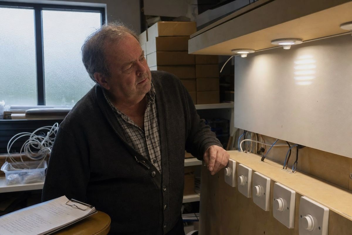
Le fait de voir la mention “ intensifiable par TRIAC ” sur une fiche technique ne vous apprend pratiquement rien sur le comportement réel du produit. Pour les projets d'éclairage B2B, la liste de contrôle pratique ci-dessous fait la différence entre un déploiement sans heurts et un entrepôt rempli de retours.
La liste de contrôle en cinq points pour vérifier la compatibilité
| Paramètre | Ce qu'il faut vérifier | Pourquoi est-ce important ? |
|---|---|---|
| Exigence relative à la charge minimale | La puissance totale des luminaires dépasse la charge minimale du variateur | La présence de LED individuelles à faible puissance dont la luminosité est inférieure au seuil entraîne un clignotement et une instabilité |
| Courant d'appel | Le circuit d'attaque limite la pointe de courant à la mise sous tension | Empêche les déclenchements intempestifs des disjoncteurs AFCI/GFCI et évite d'endommager les variateurs d'intensité lumineuse |
| Courant de maintien | Le circuit d'attaque fournit un courant suffisant au TRIAC | Élimine les coupures en milieu de cycle et le scintillement à de faibles niveaux de gradation |
| Plage de variation | Plage inférieure spécifiée, par exemple jusqu'à 1% ou 5% | Détermine s'il est réellement possible d'obtenir une gradation profonde et fluide |
| Tests de compatibilité | Le fournisseur publie une liste des variateurs testés | La preuve d'une véritable efficacité en matière de mise en relation, et pas seulement un argument marketing |
Choisissez le driver adapté au type de variateur — et au marché
Vérifiez si le projet utilise des variateurs de type « leading-edge », « trailing-edge » ou mixtes. Si la réponse est « inconnue » ou « mixte », précisez un pilote hybride avec détection automatique. Vérifiez également la tension et la fréquence du réseau électrique du marché cible. La compatibilité des drivers LED varie selon les régions : un projet japonais en 100 V se comporte différemment d'un projet allemand en 230 V, et nous effectuons les réglages nécessaires en conséquence lors de la phase de développement.
Savoir quand la coupure de phase n'est pas la solution
Je vais soulever l'objection que les acheteurs me font parfois valoir : la gradation par coupure de phase est-elle vraiment le bon choix ? Pour une modernisation à deux fils avec des commandes murales, oui : c’est simple, familier et peu coûteux à installer. Mais pour les projets nécessitant une gradation précise et poussée, des ambiances réglables ou une gestion à l’échelle du bâtiment, les protocoles 0-10 V ou DALI peuvent s’avérer plus adaptés, car ils séparent les signaux de commande de l’alimentation électrique. Une partie d’un accompagnement technique honnête consiste à indiquer à un client quand une autre architecture lui conviendra mieux. Lorsque la gradation par coupure de phase est la solution adaptée, exigez des échantillons et testez-les sur vos variateurs réels avant de vous engager sur une commande en grande quantité.
Conclusion
La gradation par coupure de phase reste la solution phare en matière de contrôle de l'éclairage, mais son succès dépend désormais de la compatibilité des alimentateurs LED. Vérifiez la charge minimale, le courant de maintien, le courant d'appel et la plage de gradation, puis effectuez des tests avant d'acheter.
Notes de bas de page
1. Wikipédia propose une présentation technique détaillée des techniques de commande par allumage par phases et de modulation sinusoïdale. ↩︎
2. L'IEEE est la principale référence en matière de normes d'ingénierie électrique pour des concepts tels que les angles de phase dans les réseaux électriques. ↩︎
3. L'ISO élabore des normes internationales relatives aux systèmes électriques et aux exigences mondiales en matière de tension du réseau électrique. ↩︎
4. Wikipédia fournit des informations complètes sur la technologie des variateurs et les facteurs qui influent sur la plage de variation. ↩︎
5. Le NIST mène des recherches techniques et élabore des normes concernant les phénomènes électriques tels que les pics de courant d'appel. ↩︎