














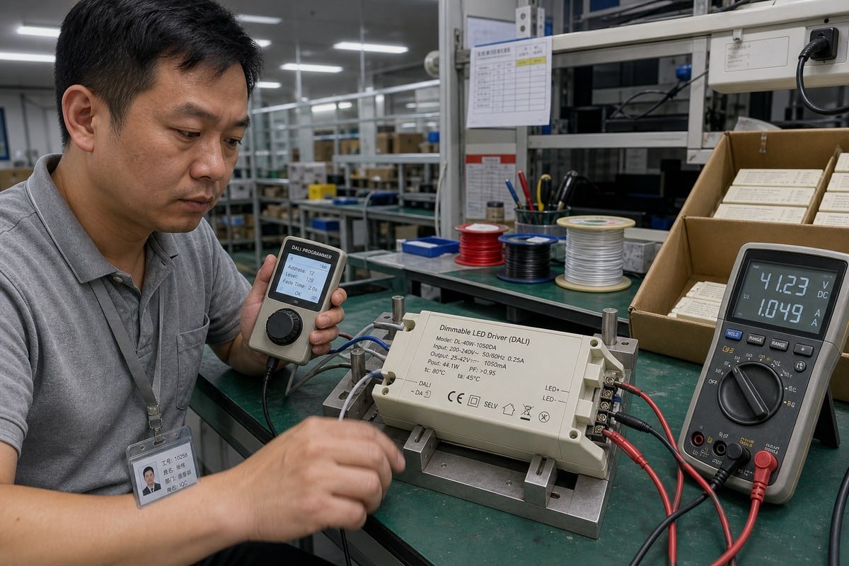
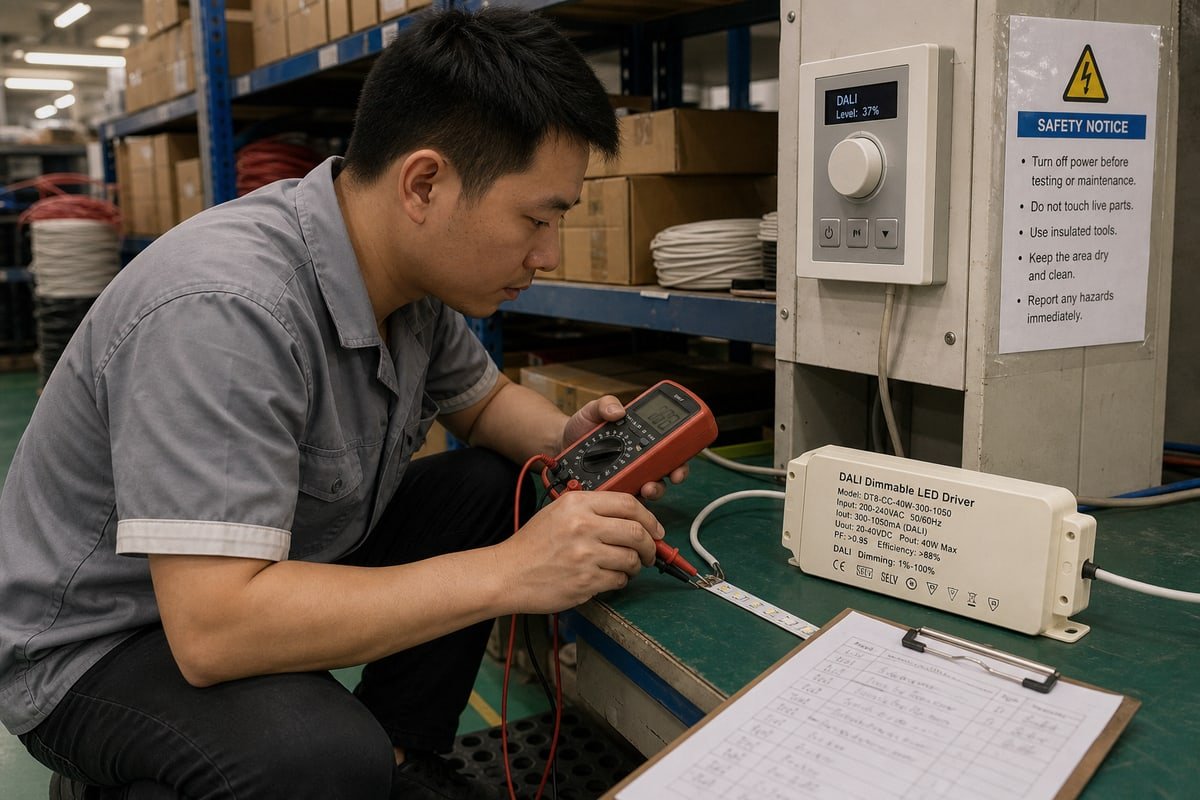
A buyer nearly rejected a shipment because his DALI commands did not produce the output current he expected. His technician measured 380 mA at 50% and assumed the drivers were faulty. That assumption almost cost him three weeks of project delay and a strained client relationship. The real problem was not the hardware at all. It was a misunderstanding of how DALI commands affect output current. Once we walked his team through the actual control chain inside our drivers, the “fault” disappeared, and so did the return request.
DALI commands specify a desired light or arc-power level, not a specific LED current. The driver’s control circuit converts that level into a regulated output current. Raising the DALI level generally increases current; lowering it reduces current, within the driver’s configured dimming range, curve, and LED load limits.
That distinction sounds small, but it changes how you troubleshoot, how you specify drivers, and how you write purchase orders. Let me break down the full chain, step by step.
How do DALI commands translate into precise output current changes?
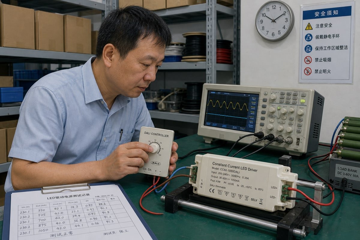
On our test bench in Shenzhen, we log output current at every DALI step before a driver ships. That data shows exactly how digital commands become regulated current.
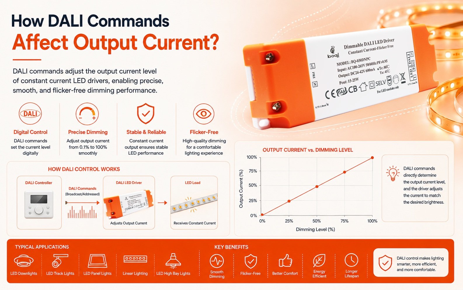
A DALI command sets a target arc-power level from 0 to 254. The driver’s control loop reads that 8-bit value, applies its dimming curve and minimum/maximum limits, then regulates the LED current to match. The command defines the operating point; the driver electronics deliver the actual current.
The full control chain looks like this: DALI command → arc-power level → driver control loop → LED current → light output. Every stage adds its own logic. A direct arc power control (DAPC) command carries an 8-bit resolution value 1 between 0 and 254. The DALI-2 standard defines a standardized logarithmic dimming curve that maps those values to output, so brightness changes appear smooth and linear to the human eye even though the current changes are not linear at all.
Three currents people confuse
| Quantity | What it represents |
|---|---|
| DALI arc-power level | The requested lighting operating level (0–254) |
| DALI bus current | Communication current on the bus, capped at 250 mA total |
| LED output current | Regulated current the driver feeds into the LED load |
The DALI bus never delivers the LED’s operating power. Each bus device draws only around 2 mA for communication. The constant current LED driver 2 supplies the real load current separately from mains input.
Why 50% DALI does not mean half current
Take our 700 mA constant current LED driver. Sending a 50% DALI level does not command 350 mA. With the logarithmic dimming curve, level 127 may correspond to only a few percent of rated current, because human eyes perceive luminous flux logarithmically. The driver may also enforce a minimum dimming level that clips the low end. So DALI level ≠ LED current. The command controls the driver’s operating point; it never directly commands “X mA.”
What should I check if DALI dimming levels don’t match expected output current?
One lesson from our early exports to Italy stuck with me: always request the driver’s configuration data before blaming the hardware. Most mismatches live in the settings.
Check the driver’s configured minimum and maximum output, its dimming curve setting, the LED load and forward voltage, whether the driver is operating in constant-current regulation, and whether the measured current is stable or mid-fade. A mismatch between DALI percentage and measured current is usually configuration, not a fault.
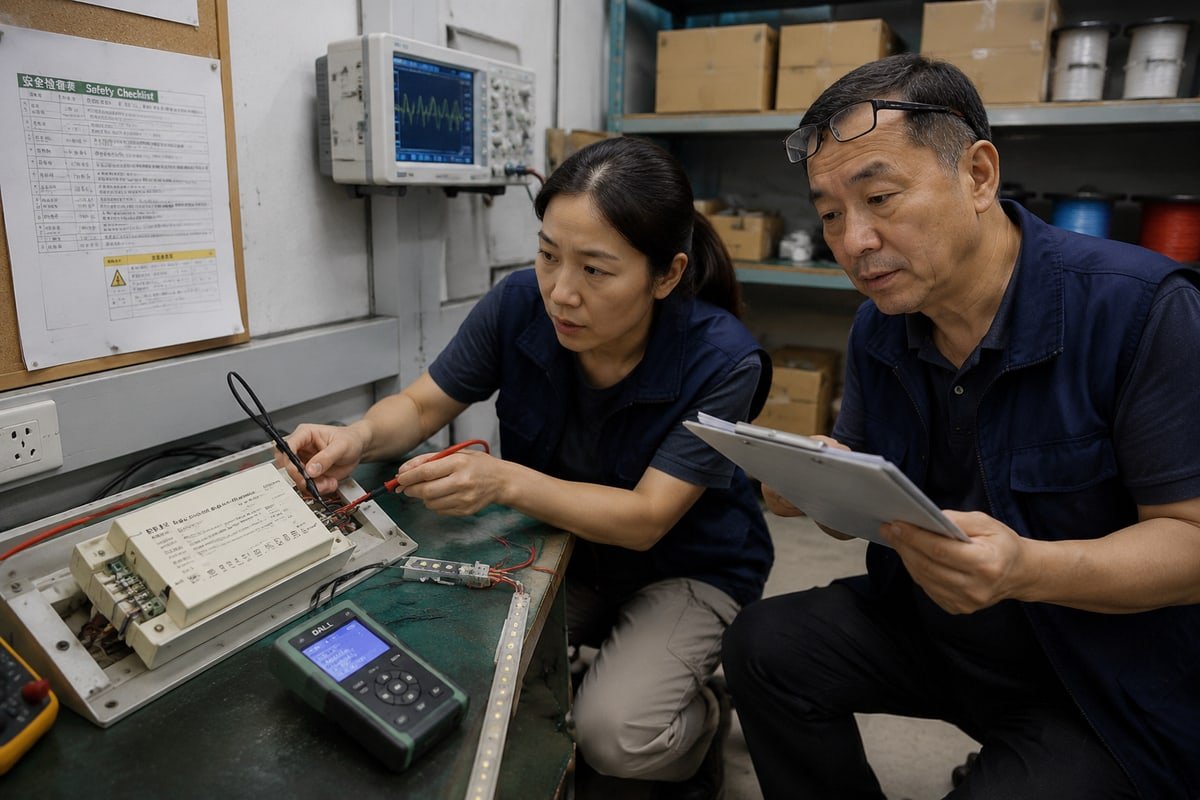
The most useful troubleshooting rule I give every engineering client is simple: never diagnose a DALI system by assuming a measured LED current should match the DALI percentage. If a technician sends 50% and reads a current that is not half the rated value, that alone proves nothing. Work through the checks in order instead.
- Confirm the programmed MIN LEVEL and MAX LEVEL. These configurable extrema mean the same command produces different currents in different installations.
- Identify the active curve. A logarithmic dimming curve and a linear dimming curve give completely different current values at the same DALI level.
- Verify the LED load. If the forward voltage sits outside the driver’s window, the driver may leave constant-current regulation entirely.
- Wait out the fade. DALI distinguishes target level from actual level, so current measured mid-fade lags the command.
- Rule out protection logic. Thermal foldback can autonomously override arc-power commands and cut current when the driver runs hot.
Symptom-to-cause quick reference
| Symptom | Most likely cause |
|---|---|
| Current lower than expected at all levels | Thermal foldback or reduced MAX LEVEL setting |
| Current stops dropping below a floor | Configured minimum dimming level reached |
| Current drifts after the command | Fade time settings still ramping the actual level |
| Flicker or color shift at deep dimming | Hybrid transition from amplitude control to pulse width modulation |
That last row matters. Many modern drivers switch from constant-current reduction to pulse width modulation at low thresholds to keep color stable, which changes what a simple multimeter reads.
How can I ensure DALI command accuracy when customizing drivers for my private-label projects?
Last spring, a procurement manager in Singapore messaged me on WhatsApp with one question: how do I guarantee every private-label driver dims identically? We built a process for that.
Lock the specification early: rated output current, minimum dimming level, dimming curve type, fade time defaults, and power-on behavior. Require DALI-2 certified control gear, approve a golden sample, and verify measured current at fixed DALI levels during production QC. Document every programmed parameter in the order contract.
In our OEM projects, dimming behavior is part of the product identity, not an afterthought. When two batches carry your logo but dim differently, your customers blame your brand, not the factory. So we treat DALI configuration data as a controlled document, exactly like the enclosure drawing or the label artwork.
Here is the process we run with private-label partners:
- Define the current setpoint method. Modern DALI-2 drivers let us set the nominal operating current, for example anywhere from 350 mA to 1050 mA, through software commands instead of DIP switches or resistors. Software programming removes mechanical tolerance and human error from the line.
- Fix the curve and limits in writing. We record the chosen dimming curve, minimum dimming level, maximum level, power-on level, and system failure level in the technical agreement before tooling begins.
- Approve a golden sample. You measure output current at agreed DALI levels, sign off, and every production unit gets compared against that reference.
- Verify at end-of-line QC. Our testers send fixed DAPC values and log the measured current for each unit, so drift shows up before packing, not after installation.
- Use query commands for traceability. Bi-directional queries let the control system read back the actual level and diagnostic data, which supports field verification after handover.
For tunable-white projects, we also lock Device Type 8 (DT8) behavior, since DT8 commands manage how current is proportioned across channels to hit a target CCT. One programmed file, applied to every unit, is what keeps your brand’s dimming feel consistent.
Which DALI command protocols should I specify to avoid output current inconsistencies across production batches?
Every OEM quotation we prepare involves a trade-off between flexibility and repeatability. The protocol details you write into the purchase order decide which one you get.
Specify IEC 62386-compliant DALI-2 control gear with the LED device type, define DAPC behavior, dimming curve (logarithmic or linear), power-on and system failure levels, and fade time settings in writing. Consistent firmware versions and programmed parameters across batches matter more than the command set itself.
The command vocabulary itself is standardized under IEC 62386 3, so any compliant DALI control gear understands the same instructions. Inconsistency creeps in through how each driver is configured to respond. That is why your specification should name both the commands and the programmed parameters behind them.
The commands and parameters that shape output current
| Command / parameter | Effect on output current |
|---|---|
| DAPC (direct arc power control) | Sets a target level 0–254; can also stop a running fade |
| STEP UP / STEP DOWN | Moves the target one step; used repeatedly in constant-light control loops |
| RECALL MAX / MIN LEVEL | Drives output to configurable extrema, so identical commands can yield different currents per installation |
| Scene recall | Jumps to one of 16 stored scene levels; a stored value of 255 means no response |
| Power-on level / system failure level | Defines the default current behavior after bus power loss or recovery |
| Fade time | Sets the slope of the current ramp, affecting control loop stability and inrush during scene transitions |
Two more details protect batch consistency. First, timing: each DALI packet takes about 25 ms, and a line supports 64 addresses, so specify group and scene commands for simultaneous changes rather than 64 sequential DAPC packets. Second, calibration data: DALI-2 memory bank commands 4 can store LED binning and lumen maintenance data, letting the driver calibrate output current dynamically so luminous flux stays uniform even when LED batches vary. We include the memory bank contents and firmware version on every batch record, because that is what makes unit 5,000 dim exactly like unit 1.
Conclusion
DALI commands set arc-power levels; your driver’s design, curve, and configuration decide the output current. Specify those parameters precisely, and every batch will dim exactly as planned.
Footnotes
1. Explains the digital protocol structure and command resolution used in DALI systems. ↩︎
2. Provides technical background on how constant current circuits regulate power for LED loads. ↩︎
3. The international standards body that publishes the IEC 62386 series for lighting control. ↩︎
4. Official industry body for DALI-2 standards and protocol specifications. ↩︎