















Buyers keep asking our Shenzhen engineering team how to match TRIAC dimmers with CV drivers after a flickering installation. One mismatched spec sheet can sink an entire lighting project.
To match a TRIAC dimmer with a constant-voltage LED driver, choose a driver explicitly rated for TRIAC/phase-cut dimming, match its output voltage to the LED load, and confirm the phase-cut type, load range, and dimming range align with the dimmer. Voltage matching alone never guarantees flicker-free dimming.
That short answer hides a lot of engineering detail. Two products can both say TRIAC dimmable and still perform badly together. In this guide, I will walk you through the specifications, the failure modes, the testing process, and the exact requirements you should put in a purchase order. My goal is simple: help you treat compatibility as a chain, not a label.
What technical specifications should I check to confirm my TRIAC dimmer works with a CV driver?
Last spring, our QC line in Shenzhen rejected a driver batch that dimmed perfectly on one wall dimmer and stuttered badly on another. Both datasheets said TRIAC dimmable.
Check five specifications: the driver's explicit TRIAC/phase-cut dimming rating, the supported phase type (leading-edge or trailing-edge), the dimmer's minimum and maximum load window, the driver's output voltage against your LED load, and the manufacturer's tested dimmer compatibility list.
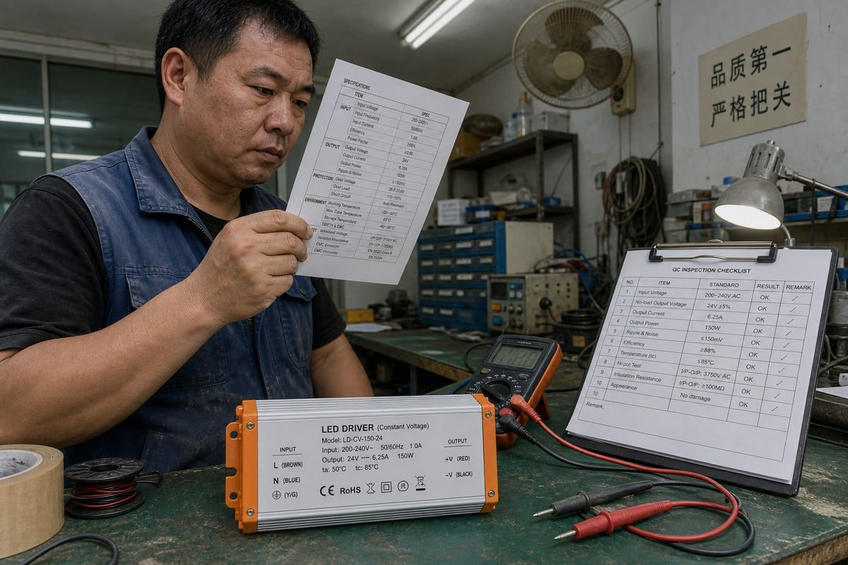
The core matching formula I give every buyer is simple: TRIAC dimmer → TRIAC/phase-cut compatible CV driver → matching-voltage LED load. A concrete example: a 120/230V AC TRIAC dimmer feeds a 24V TRIAC-dimmable CV driver, which powers a 24V LED strip. Break any link in that chain and dimming fails. A standard constant-voltage driver 1 cannot interpret a chopped AC waveform. It will refuse to dim, flicker immediately, or shut down. So the words "phase-cut" or "TRIAC dimmable" must appear on the driver's label, like the spec printing we place on the top face of our aluminum-cased units.
The Specification Chain
| Specification | Where to find it | What to confirm |
|---|---|---|
| Phase-cut dimming rating | Driver datasheet or casing print | Says TRIAC, phase-cut, or forward-phase explicitly |
| Phase type | Dimmer and driver datasheets | Leading-edge and trailing-edge support match |
| Load window | Dimmer datasheet | Driver input load sits inside min and max LED-rated range |
| Output voltage | Driver output label | Matches 12V or 24V LED strips exactly |
| Compatibility list | Manufacturer website | Your exact dimmer model appears as tested |
Leading Edge vs Trailing Edge
The leading edge vs trailing edge distinction matters most. Most CV TRIAC drivers, including the standard versions we build, are designed primarily for leading-edge, forward-phase dimmers. Some can be customized for trailing-edge, reverse-phase use. This maps loosely onto ELV vs MLV dimmers: MLV dimmers use leading-edge phase-cut dimming 2, while ELV dimmers use trailing-edge. Pairing a leading-edge-only driver with an ELV dimmer risks buzzing, excess heat, or component failure. Never assume one covers the other.
Also confirm the driver dims its DC side using a PWM output signal. PWM is the industry-standard method for dimming constant-voltage loads because it holds color temperature steady across the range.
Why does my LED lighting flicker or buzz when I pair a TRIAC dimmer with a constant voltage driver?
A procurement manager in Singapore once sent me a WhatsApp video of buzzing pendant lights. Her installer blamed the LED strips. Our bench test found the real culprit in minutes.
LED lighting flickers or buzzes because the TRIAC cannot maintain its holding current at low conduction angles, usually due to insufficient load, a missing active bleeder circuit, a low PWM frequency, or a phase-type mismatch between the dimmer and the constant voltage driver.
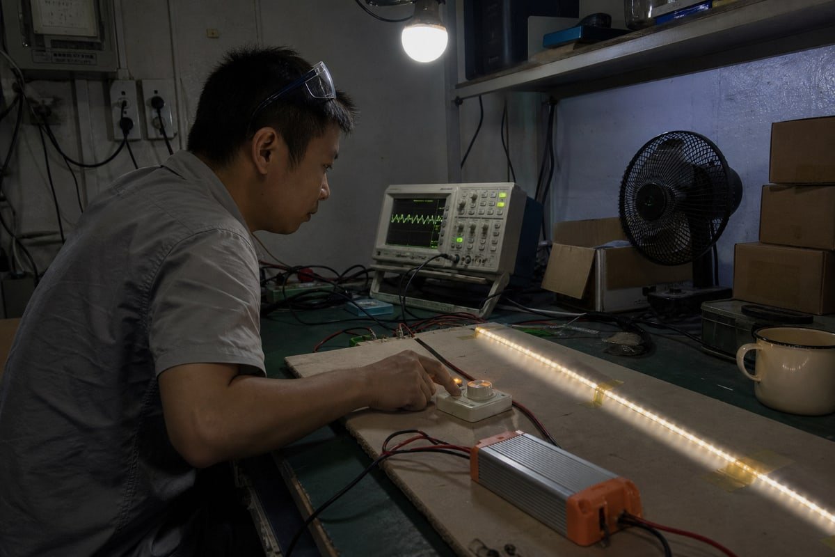
The root problem is history. TRIAC dimmers were originally built for incandescent bulbs, which draw heavy, resistive current. A modern dimmable LED power supply draws far less current and behaves very differently at its input stage. A TRIAC needs a certain latching current to fire and a holding current to stay conducting. When the LED load is too light, the TRIAC misfires or drops out mid-cycle. The result is visible shimmer, dropout at low conduction angles, or lights that refuse to turn fully off.
This is why well-designed drivers include an integrated active bleeder circuit. The bleeder draws just enough current to keep the TRIAC latched even when the LEDs are dimmed very low. Our engineers tune this circuit carefully because too little bleed causes flicker and too much wastes power as heat.
Symptom-to-Cause Map
| Symptom | Likely cause | Practical fix |
|---|---|---|
| Flicker at low levels | Holding current not maintained | Driver with active bleeder; increase load |
| Audible buzzing | Phase-type mismatch or coil vibration | Match leading or trailing edge correctly |
| Dead zone before turn-on | Poor low-end waveform interpretation | Specify tested low-end dimming point |
| Dropout when dimmed deep | Low conduction angle starves TRIAC | Raise minimum load; adjust dimmer trim |
| Shimmer on camera | Low PWM frequency | Specify PWM output above 3kHz |
The last row matters more than most buyers realize. A PWM frequency above 3kHz eliminates the stroboscopic wagon-wheel effect 3, which is essential for flicker-free performance in retail spaces with video recording or environments with moving machinery. One more nuance: the repetitive hard starts of a phase-cut waveform stress the driver's input capacitors far more than a steady AC feed does, so inrush current protection directly affects driver lifespan, not just breaker tripping.
How do I test dimming compatibility before I approve a bulk production order with my supplier?
Early in our export business, we shipped drivers to a project in Italy based on datasheets alone. That painful project taught us why a sample test beats a compatibility label every time.
Test the exact dimmer, driver, and LED load combination you plan to install. Run it at full brightness, minimum brightness, and through slow fades for at least 30 minutes, watching for flicker, buzz, dead zones, dropout, and inconsistent low-end points before approving production.

Two datasheets both marked "TRIAC dimmable" do not guarantee good results together. Compatibility is strongest when both the dimmer maker and the driver maker list the exact model combination as tested. Use those lists as your first filter, then confirm with a physical test. Here is the protocol we run on our own bench in Shenzhen before we release any OEM batch, and it is the same protocol I recommend buyers repeat on their side.
- Request golden samples. Get the exact driver revision that will go into mass production, not a lab prototype. Small input-stage changes between revisions can change dimming behavior.
- Wire correctly. Place the TRIAC dimmer only on the primary AC side of the driver. Any phase-cut control on the secondary DC side will damage the output stage and the LED load.
- Load realistically. Connect the intended number of 12V or 24V strips at the real circuit length. Load level changes TRIAC behavior, so a one-meter test strip proves nothing about a forty-meter installation.
- Sweep the range. Hold full-on for ten minutes, then dim to the lowest point, then run slow fades up and down. Film the low-end on a phone camera to catch shimmer your eye misses.
- Test multiple dimmer brands. If your market mixes dimmer brands, test each one. Minimum brightness can differ between dimmers even with the same driver.
- Check startup and inrush. Switch the circuit on and off twenty times. Weak inrush current protection shows up here as delayed starts, flashes, or nuisance breaker trips.
- Document everything. Record the dimmer model, driver serial, load wattage, and low-end behavior. This record becomes your acceptance criteria for the bulk order.
When a buyer follows this process with us before signing, disputes after delivery essentially disappear. When they skip it under deadline pressure, we usually end up troubleshooting by video call three weeks later.
What minimum load and dimming curve requirements should I specify when sourcing CV drivers for TRIAC systems?
Every driver we quote involves a trade-off: tighter load matching improves dimming depth, while extra headroom improves thermal life. Writing the specification well balances both sides.
Specify a dimmer minimum load requirement of 20–40W that your connected LED wattage must exceed, a driver sized with roughly 120% wattage headroom over the load, a smooth logarithmic dimming curve, a low-end point near 1%, and no visible dead zone.

The minimum load requirement is the most ignored line in any TRIAC sourcing spec, and it causes the most returns. Many wall dimmers need a minimum connected load, with typical cited values of 20W–40W for certain installations. High-efficiency LED circuits can easily fall below that floor, especially on small bedroom or corridor circuits. When they do, the TRIAC starves and the lights shimmer. Your spec should state the smallest real circuit wattage in the project and require stable dimming at that load.
Sizing involves genuine tension between two rules of thumb. Some strip-light guidance targets loading the driver at 90–95% of capacity for the tightest load matching and best dimming behavior. Procurement guidance, on the other hand, often recommends roughly 120% driver wattage versus fixture load 4 for thermal margin. Both views have merit. Our position after years of OEM projects: for TRIAC-dimmable units, lean toward headroom. TRIAC-compatible drivers typically run 10–15% hotter than non-dimmable versions because they dissipate energy internally to stabilize the chopped input. That is exactly why our casings use a ribbed heat-sink profile. Extra headroom protects lifespan; you can preserve low-end dimming quality through the bleeder design instead.
Specification Lines to Put in Your Purchase Order
| Requirement | Value to specify | Why it matters |
|---|---|---|
| Dimmer minimum load | 20–40W, per dimmer datasheet | Prevents TRIAC starvation and flicker |
| Driver headroom | ~120% of connected load | Offsets 10–15% extra thermal stress |
| Dimming curve | Logarithmic (perceptually smooth) | Matches how eyes perceive brightness |
| Low-end point | Defined, ideally near 1% | Avoids dead zones and abrupt cutoff |
| PWM frequency | Above 3kHz | Ensures camera-safe, flicker-free output |
| Dimming range compatibility | Tested against named dimmer models | Guarantees consistent low-end across brands |
One Large-Project Warning
For big commercial installations, add a note on neutral wire saturation. TRIAC dimming creates non-linear loads 5, and neutral current can exceed phase current across many circuits. Oversized neutral conductors may be required to prevent overheating. Flag this to the electrical engineer early; it is much cheaper on paper than in conduit.
Conclusion
Mismatched labels cause flicker, returns, and missed deadlines. Match phase type, load window, voltage, and dimming curve, then test the exact combination before you ever approve bulk production.
Footnotes
1. ISO standards provide the framework for quality and safety in the manufacturing of electrical control gear and drivers. ↩︎
2. Wikipedia provides a technical overview of phase-cut dimming methods, including leading-edge and trailing-edge control for various loads. ↩︎
3. IEEE 1789 standards define the limits for stroboscopic effects to ensure user safety and health in lighting. ↩︎
4. The Department of Energy offers guidelines on LED system efficiency and proper load management for dimming applications. ↩︎
5. Authoritative Wikipedia entry defining non-linear loads and their impact on power quality. ↩︎